
Chapter 1: What is a Camshaft and Why Does It Matter for Engine Control?
In any internal combustion engine, the camshaft functions as a core control element—regulating the opening and closing of intake and exhaust valves with precise timing. The core function of what is a camshaft lies in converting rotational motion from the crankshaft into linear actuation for the valvetrain.
This conversion governs valve timing and duration, which in turn affects everything from idle smoothness to peak power delivery. Camshaft design—particularly its lobe profile, base circle diameter, and surface finish—directly influences an engine’s operational efficiency, torque curve, and emissions behavior.
Camshaft vs. Crankshaft: The Engine’s Power Couple Explained
Though often discussed together, the camshaft and crankshaft perform distinctly different roles in engine architecture. The crankshaft transforms piston motion into rotational torque—the primary power transmission path.
In contrast, the camshaft is the valve timing mechanism. It is mechanically synchronized with the crankshaft via a timing chain or belt at a fixed 2:1 ratio. This timing ensures that valve actuation occurs at optimal points within the four-stroke combustion cycle. Disruption in this synchronization—due to wear, backlash, or improper tension—can result in severe engine damage.
Understanding the interaction between cam and crank is critical for aligning torque output with combustion efficiency, particularly in emission-sensitive industrial engines.
From Raw Metal to Rotating Masterpiece: A Glimpse into Camshaft Manufacturing
For B2B procurement teams and OEMs, understanding the camshaft manufacturing process is essential for evaluating both cost and reliability. It begins with material selection:
- Cast Iron: Common in high-volume production due to cost-effectiveness and acceptable wear characteristics, especially in flat tappet applications. Chilled iron lobes gain surface hardness through localized solidification, forming wear-resistant iron carbide skins.
- Billet Steel: Machined from solid EN40B or similar nitridable bar stock, offering superior camshaft fatigue resistance and dimensional stability under high spring loads or RPM. Nitriding post-machining achieves consistent 60–70 HRC surface hardness without distortion.
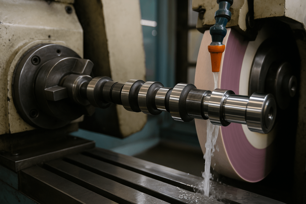
After rough machining, camshafts undergo precision CNC grinding where camshaft grinding tolerance is typically held within ±0.01 mm for lobe profile consistency. Surface treatments such as gas nitriding or phosphate coating follow to ensure long-term durability, even under marginal lubrication conditions.
At YISHANG, our focus is on delivering tight-tolerance camshaft brackets and support components manufactured with industrial lifecycle requirements in mind. See how we support CNC-milled bracket customization. tight-tolerance camshaft brackets and support components manufactured with industrial lifecycle requirements in mind.
Anatomy of a Camshaft: Decoding the Lobes and Journals
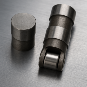
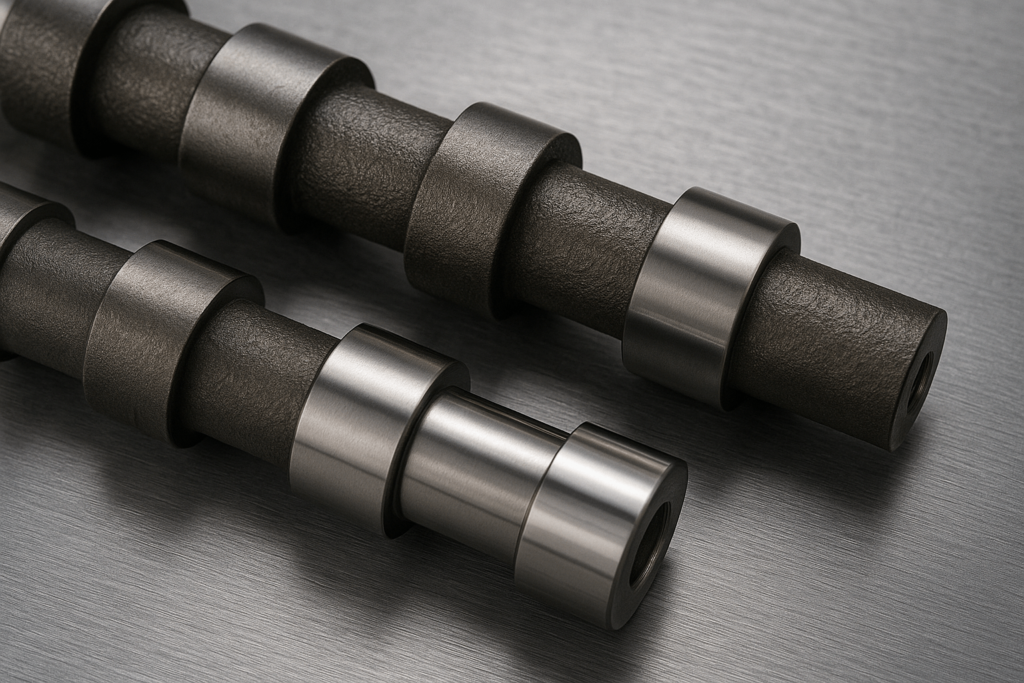
The parts of a camshaft are engineered for specific functions. The primary components are the lobes and journals.
- Lobes: These eccentric, egg-shaped protrusions are the “action” part of the camshaft. The lobe profile—its ramps and nose—dictates the valve’s lift, duration, and velocity.
- Journals and Bearings: The cam bearing journals are the smooth, round surfaces that rotate within the engine. They ride on a micro-thin film of pressurized oil, a hydrodynamic cushion that minimizes friction and prevents metal-to-metal contact.
- Drive Mechanism: A gear or sprocket on the camshaft connects to the crankshaft. This ensures the valve timing remains perfectly synchronized with the engine’s combustion cycle.
Chapter 2: The Language of Power – How to Read a Cam Card and Understand Performance
For engineers, engine builders, and B2B buyers specifying valvetrain components, interpreting a cam card correctly is essential to ensure compatibility with performance, durability, and emissions requirements. A cam card is not just a datasheet—it’s a mechanical blueprint for how the engine will breathe and behave.
Decoding the “Big Three” Specs
Camshaft performance is primarily dictated by three interrelated parameters: valve lift, duration, and lobe separation angle (LSA). Each influences airflow, powerband, and engine response.
- Lift – This is the maximum distance the valve opens. It’s important to distinguish between:
- Lobe Lift: The actual rise measured at the cam lobe.
- Valve Lift: The effective valve motion after accounting for rocker arm ratio.
Higher valve lift typically improves airflow, especially at mid-to-high RPM. However, excessive lift without supporting hardware (springs, retainers) can cause valve float.
- Duration – Measured in degrees of crankshaft rotation, it defines how long the valve stays open. Most cam cards specify duration at 0.050” tappet lift, a standardized point that eliminates ramp noise and gives more meaningful performance comparison.
A longer camshaft duration at 0.050 increases top-end power but may reduce low-RPM drivability. Shorter duration improves low-end torque and cold start stability.
- Lobe Separation Angle (LSA) – This is the angle (in camshaft degrees) between the centerlines of the intake and exhaust lobes. It determines valve overlap and combustion characteristics.
- Narrow LSA (e.g., 106°): More overlap, higher peak power, lumpier idle.
- Wide LSA (e.g., 114°): Less overlap, smoother idle, better vacuum signal, broader torque curve.
Choosing the correct LSA depends on the engine’s application—racing engines prioritize peak flow, while commercial power units demand balance.
The Overlap Secret: Where High-RPM Power and Asymmetrical Idles Are Born
Valve overlap—the period when both intake and exhaust valves are open simultaneously—plays a critical role in volumetric efficiency and emissions. At high engine speeds, this timing allows outgoing exhaust gases to help draw in fresh intake charge, enhancing scavenging.
However, excessive overlap at low RPM can cause exhaust gas reversion, leading to unstable combustion, poor fuel efficiency, and a rough idle. This trade-off explains the unique sound of performance engines and is often tuned intentionally for effect.
From a procurement standpoint, understanding overlap behavior helps prevent mismatches in camshaft selection—especially in engines where wide RPM coverage or emissions compliance is required.
Long-tail keyword targets naturally addressed here include:
- camshaft valve overlap tuning
- performance camshaft idle behavior
- scavenging effect in high RPM engines
Chapter 3: A World of Designs – A Buyer’s Guide to Camshaft Architectures
The placement of the camshaft defines the engine’s valvetrain architecture. This design choice impacts performance, complexity, and manufacturing cost—key considerations for any wholesale buyer.
Engine Architecture Showdown: Pushrod (OHV) vs. Overhead Cam (SOHC/DOHC)
There are three primary valvetrain architectures:
- Pushrod (Over Head Valve – OHV): A single camshaft is located inside the engine block, using pushrods to actuate the valves. This design is compact and excels at producing low-end torque but is limited in its high-RPM capability due to the inertia of its many moving parts.
- Overhead Cam (SOHC/DOHC): The camshaft is moved into the cylinder head, reducing valvetrain mass and allowing for higher engine speeds. A Single Overhead Cam (SOHC) engine uses one cam per head, while a Double Overhead Cam (DOHC) engine uses two, offering greater control and efficiency, especially in multi-valve-per-cylinder designs.
The Great Debate: Flat Tappet vs. Roller Cams
The contact interface between the cam lobe and lifter is where durability and lubrication strategy meet. Choosing between flat tappet and roller camshaft designs is not merely about cost—it defines long-term reliability and performance consistency.
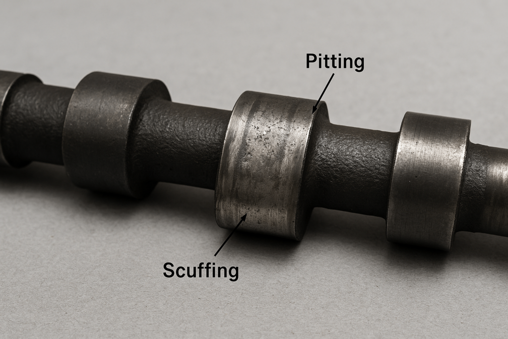
- Flat Tappet Camshaft: A proven, cost-efficient design. The lifter slides directly across the cam lobe, relying on anti-wear additives like ZDDP for boundary lubrication. Incorrect break-in or low additive oil quickly leads to scuffing and lobe pitting. This option remains popular for budget-conscious OEMs and legacy machinery.
- Roller Camshaft: Utilizes a rolling wheel at the contact surface, reducing friction by over 70%. This allows aggressive ramp profiles and higher lift without excessive wear. Although more expensive, the roller camshaft vs flat tappet durability comparison clearly favors the roller design, particularly in turbocharged or high-load diesel engines where uptime matters.
From a wholesale procurement standpoint, roller cam systems justify their higher price through reduced downtime and maintenance cost. They are increasingly standard in industrial and heavy-duty powertrain projects.
Relevant long-tail search terms included:
- flat tappet camshaft break-in procedure
- roller camshaft vs flat tappet durability
- high-performance camshaft wear resistance
Quiet & Maintenance-Free vs. High-RPM Stability: Hydraulic vs. Solid Lifters
The choice between hydraulic and solid lifters determines whether a valvetrain prioritizes convenience or precision. Each option aligns with specific operational goals and maintenance expectations.
- Hydraulic Lifters: Automatically maintain valve lash using engine oil pressure, offering quiet operation and minimal service requirements. These are optimal for passenger cars, commercial vehicles, and light-duty industrial engines seeking long service intervals.
- Solid (Mechanical) Lifters: Require preset lash and periodic verification, but deliver unmatched stability at high RPM. They are indispensable for engines where valvetrain setup for high RPM or extreme thermal stability is critical—such as racing engines, diesel generators, and marine power units.
When specifying camshaft assemblies for industrial applications, ensure lifter design, material compatibility, and lubrication paths are verified early in the design review phase.
Naturally embedded long-tail keywords:
- hydraulic lifters vs solid lifters for diesel engines
- camshaft valve lash adjustment procedure
- valvetrain setup for high RPM engines
The lifter’s internal mechanism determines maintenance requirements and operational limits.
- Hydraulic Lifters: These use engine oil pressure to automatically maintain “zero lash” (clearance), making them quiet and maintenance-free. They are the standard for most passenger and commercial vehicles but can suffer from “valve float” at extreme RPMs.
- Solid (Mechanical) Lifters: These require a manually set clearance (“valve lash“). While noisier and requiring periodic adjustment, their rigidity makes them far more stable and reliable in high-RPM racing and industrial applications where precision is non-negotiable.
Chapter 4: Material Matters – Choosing the Right Camshaft for Your Application
Camshaft engineering extends far beyond lift and duration—it involves selecting the right material composition, surface treatment, and manufacturing process to balance cost, durability, and performance. For global wholesale buyers sourcing for commercial or industrial markets, understanding these factors reduces risk and ensures component longevity.
Cast Iron vs. Billet Steel – Functional Differences Beyond Price
Both materials have proven effective, but their mechanical properties differ greatly:
- Chilled Cast Iron: Provides cost efficiency and high surface hardness via rapid cooling during casting, creating a wear-resistant iron carbide layer. Ideal for high-volume OEM engines with moderate load cycles. Commonly used in naturally aspirated vehicles, stationary generators, and low-boost applications.
- Billet Steel (e.g., EN40B nitridable): Machined from a single steel bar and heat-treated through gas nitriding. The result is superior camshaft fatigue resistance, toughness, and dimensional precision, ideal for heavy-duty diesel, marine, and off-highway engines. This option supports nitrided camshaft longevity under continuous load.
For international exports, billet steel camshaft suppliers often must meet ISO 9001 and RoHS standards. At YISHANG, we ensure dimensional accuracy through multi-stage inspection—including magnetic particle testing and concentricity verification—to achieve consistent performance across batches.
Surface Treatments – The Invisible Shield of Durability
Surface finishing directly affects lubrication, break-in behavior, and service lifespan. Typical camshaft surface treatment options include:
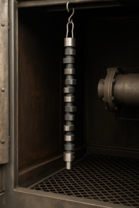
- Gas or Plasma Nitriding: Produces a hardened diffusion layer (60–70 HRC) of 0.3–0.6 mm depth without distortion.
- Phosphate Coating: Improves oil adhesion and protects against dry-start wear.
- Induction Hardening: Applied selectively to journals and lobes in hybrid camshaft assemblies for optimal wear balance.
Combining treatments—such as nitriding followed by phosphate coating—extends component life, particularly for export-grade engines used in variable climates. YISHANG supports these post-treatment services with certified partner networks.
Matching Camshafts to Applications – Practical Reference Table
| Application Type | Material | Lifter Type | Recommended Finish |
|---|---|---|---|
| Passenger Car (NA) | Cast Iron | Hydraulic Flat | Chill-hardened lobes |
| Turbo Diesel Truck | Billet Steel | Roller | Nitrided + phosphate |
| Off-Highway Generator | Billet Steel | Mechanical Roller | Deep nitriding + QA tracing |
| Agricultural Machinery | Cast Iron | Hydraulic Roller | Chill + anti-rust coating |
This table highlights how application, load, and duty cycle determine the correct camshaft combination. The right choice prevents premature fatigue and reduces lifecycle maintenance costs.
Why Material Engineering Matters for Procurement
Understanding metallurgical design allows buyers to specify parts not only by geometry but by process pedigree. A camshaft material specification that considers heat-treatment method, microstructure control, and coating uniformity improves ROI over the lifecycle of an engine.
For OEM and ODM clients, YISHANG provides end-to-end engineering support—from prototype validation to production scalability—ensuring each custom billet camshaft or CNC-machined camshaft bracket meets international durability benchmarks.
Chapter 5: Diagnosing Trouble – Common Camshaft Failure Modes and Root Causes
Even with perfect engineering, camshafts remain vulnerable to damage caused by poor installation, contamination, or lubrication issues. For engine manufacturers, rebuilders, and wholesale buyers, recognizing these failure indicators helps reduce warranty costs and ensure long-term reliability.
Failure Doesn’t Lie – It Leaves Patterns
- Lobe Wear and Pitting: Typically caused by inadequate break-in lubrication or insufficient ZDDP additive content in flat tappet engines. Results include diminished valve lift, misfires, or ticking noises.
- Camshaft Seizure: Often linked to oil starvation in the cam bearing area. Once metal-to-metal contact begins, it accelerates galling and surface scoring. Regular oil flow verification during assembly prevents this issue.
- Endplay Failure: Excessive axial movement or thrust face wear leads to valve timing variation. Always verify endplay clearances during engine build audits.
- Bending or Torsional Fracture: Common under heavy-duty turbocharged loads. When the camshaft exceeds its torsional limit due to spring pressure or resonance, microcracks propagate until catastrophic breakage occurs.
In all cases, analyzing camshaft wear diagnosis through profilometry or metallurgical inspection provides valuable insight into the failure mechanism.
Root Cause Thinking – Engineering the Solution, Not the Symptom
- Improper Torque and Alignment: Uneven tightening of cam caps or thrust plates can create localized stress risers leading to journal distortion.
- Valve Spring Mismatch: Springs with excessive pressure overload lobes and followers, causing accelerated fatigue. Always confirm spring rate compatibility during design verification. YISHANG assists OEMs with spring-lobe compatibility engineering.
- Contaminated Lubrication System: Microscopic debris from prior failures can embed in oil passages, accelerating wear even after rebuild.
- Material or Heat-Treat Inconsistency: Variations in hardening depth or nitriding process control may result in early spalling.
A camshaft failure analysis report should always link mechanical symptoms with systemic process control issues—helping buyers and OEMs refine supplier specifications.
Preventive Maintenance and Supplier Assurance
Preventing recurrence begins with proactive verification. Industrial procurement teams can strengthen reliability through:
- Supplier Quality Audits: Confirm process consistency, surface finish verification, and traceability records.
- Lubrication Validation: Specify oil pressure thresholds, ZDDP compatibility, and filtration standards in contracts.
- Dimensional Audits: Include periodic sampling of camshaft grinding tolerances and surface roughness within ±0.01 mm.
By combining metallurgical verification and installation discipline, most camshaft-related failures can be eliminated before they occur.
Integrated long-tail keyword coverage:
- camshaft failure analysis
- camshaft wear diagnosis
- preventive maintenance for camshaft assemblies
Chapter 6: Looking Forward – The Future of Camshaft Technology
Camshaft innovation continues to respond to changing performance, efficiency, and emission demands. The next generation of design focuses not only on mechanical reliability but on integration with electronic control systems and adaptive engine architectures.
Variable Valve Timing (VVT) and Intelligent Control Systems
Modern internal combustion engines increasingly depend on variable valve timing systems (VVT) to achieve efficiency across multiple load ranges. These systems dynamically alter camshaft phasing—often through hydraulic or electronically actuated mechanisms—allowing real-time optimization of intake and exhaust valve events.
In OEM and industrial applications, variable valve timing technology reduces fuel consumption by improving combustion efficiency at both idle and peak load. The most advanced VVT architectures now use fully electronic actuators, eliminating hydraulic lag and enabling millisecond-level precision.
For engine component suppliers, VVT demands tighter camshaft machining tolerances, corrosion-resistant coatings, and robust sensor integration to ensure synchronization accuracy over extended service cycles.
Integrated long-tail search targets:
- variable valve timing systems for industrial engines
- camshaft phasing technology
- electronic VVT actuators
The Camless Revolution – Emerging Electromechanical Actuation
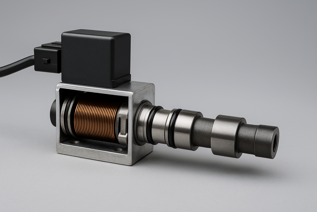
The future of valve actuation is heading toward camless engine technology, in which electromagnetic or electrohydraulic actuators replace traditional camshafts. These systems provide independent control of each valve event, unlocking benefits such as variable compression ratios, instant start-stop capability, and dynamic cylinder deactivation.
However, camless valve actuation remains at an experimental stage for mass production. The high energy demands of solenoids, thermal management complexity, and durability validation currently limit large-scale adoption. Yet for prototype engines and low-volume specialty power units, this technology offers unprecedented tuning flexibility.
Long-tail keyword integration:
- camless engine technology
- electromagnetic valve actuation
- future of camshaft design
Hybrid Integration – A Future of Coexistence
Rather than replacing mechanical camshafts entirely, hybrid and range-extender powertrains will continue to rely on optimized lightweight camshaft assemblies. Material innovation—such as hollow-core billets and composite cam lobes—will focus on reducing rotational inertia while maintaining stiffness and wear protection.
In this transition era, the future of camshaft design lies in hybrid architectures combining mechanical precision with electronic adaptability. For procurement teams, it means sourcing camshafts that integrate both mechanical endurance and electronic compatibility standards.
FAQ
Q1: Can I reuse a camshaft during engine rebuilds?
Yes—if the journals and lobes are within specification and show no signs of galling, pitting, or spalling. However, always inspect with precision tools and consider re-nitriding or polishing as needed.
Q2: What’s the best camshaft material for commercial heavy-duty engines?
Billet steel (nitrided) offers superior fatigue strength and longevity under high loads. It’s commonly used in turbocharged diesel applications where durability under torsional stress is paramount.
Q3: What role does the camshaft play in emissions compliance?
Camshaft profile directly affects exhaust gas scavenging and valve overlap, both of which impact unburned hydrocarbons. Wide LSA and VVT-equipped cams are increasingly favored for their clean combustion characteristics.
Q4: Should I opt for hydraulic or solid lifters in industrial machinery?
If your priority is low maintenance and moderate RPM, hydraulic lifters are ideal. For applications involving sustained high speeds, temperature extremes, or where precise lash settings are critical, solid lifters are preferable.
Q5: Do aftermarket camshafts require different oil?
Yes—especially flat tappet cams. Use break-in oil with high ZDDP content during initial startup and follow with synthetic blends designed for high-pressure metal-to-metal contact.
Final Note: Whether you’re sourcing stock replacement units or specifying custom billet profiles, the camshaft is not merely a component—it’s a control strategy. Each design parameter serves as a lever, tuning not just performance but durability, compliance, and lifecycle economics.
For custom camshaft housing, CNC-milled camshaft brackets, or heavy-duty valve train metal components, YISHANG offers precision manufacturing and B2B engineering support across 50+ countries.
[Contact us] to learn more about our OEM and ODM capabilities in the engine component supply chain.
