
Introduction: Solve Spot Weld Failures Before They Start
Struggling with inconsistent spot welds or rising defect rates in outsourced sheet metal parts? You’re not alone.
In high-volume manufacturing, the integrity of small components often dictates large-scale outcomes. For sheet metal assemblies, this means spot welds—the hidden anchors of reliability and strength.
A single automotive body may contain thousands of these welds, and each must be repeatable, clean, and robust. For procurement engineers and OEM sourcing teams, mastering Resistance Spot Welding (RSW) is a smart investment in both product and supply chain integrity.
This technical guide delivers manufacturing-ready insights for engineers and purchasing teams. It provides actionable guidance to help you specify, evaluate, and source custom sheet metal parts with consistent spot weld quality.
1. The Engineer’s Design Rulebook: 4 Unbreakable DFM Golden Rules for Spot Welding
Before production begins, the success of a spot-welded assembly is determined on the design floor. Adhering to Design for Manufacturability (DFM) principles is a prerequisite for creating a cost-effective and robust product.
For wholesale purchasers, specifying parts that meet these DFM guidelines is the most direct way to reduce costs, shorten lead times, and improve batch consistency.
1.1 Rule #1: Weld Spacing (Pitch)
The distance between adjacent spot welds, known as pitch, directly impacts the structural integrity of the final assembly. If welds are placed too close, the electrical current for a new weld may be diverted through an existing weld.
This phenomenon, current shunting, reduces energy at the intended weld interface, producing an undersized and dangerously weak weld—even with correct machine settings.
To prevent this defect, follow the guideline: the center-to-center distance between spot welds should be greater than 10 times the sheet thickness (10t). This ensures each weld receives the necessary current to create consistent strength across the production batch.
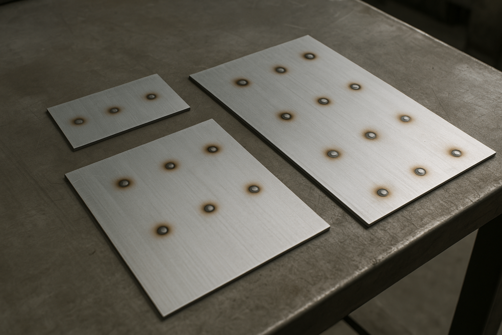
1.2 Rule #2: Weld Edge Distance
Just as welds should not be placed too close to each other, they also must be adequately spaced from the part’s edge. A weld near a free edge creates a weak point, as the surrounding material lacks the thermal mass to contain the molten nugget.
This often results in “blowout,” where molten metal is expelled, compromising the joint and distorting the edge.
To avoid this, ensure the center of the spot weld is placed at least 6.0 mm from the nearest edge. This provides a stable perimeter of cooler parent material, helping the nugget form properly and carry its intended structural load.
1.3 Rule #3: Flange Overlap Width
A secure weld requires a stable base. The flange—where two sheet metal pieces overlap—must be wide enough to support electrode positioning and contain the weld nugget.
If the flange is too narrow, the electrodes may slip or deform the edge, resulting in inconsistent welds. This design flaw can lead to line stoppages and costly rework.
For example, welding 1.25 mm low-carbon steel should use a minimum flange overlap of 14 mm (9/16 in). This ensures repeatability, stability, and weld strength.
1.4 Rule #4: Tool Accessibility
Even a theoretically perfect joint is useless if welding tools can’t reach it. Engineers must factor in the entire welding system—robotic arm, welding gun, and electrode shanks—during the design phase.
Deep pockets or tall flanges can obstruct access, forcing the use of costly custom tools.
Maintain a clearance of at least 3.0 mm around the weld tool shank to ensure standard electrodes can operate efficiently. Tool-friendly designs directly contribute to production cost control and schedule reliability.
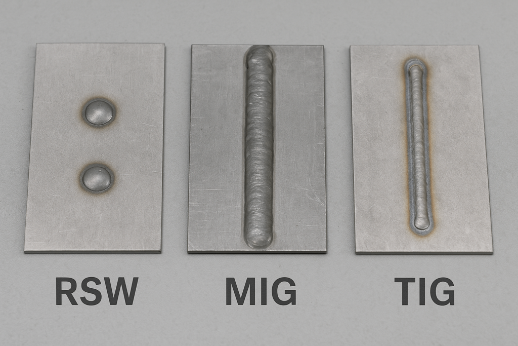
2. Process Showdown: Spot Welding vs. MIG/TIG – When and Why to Choose?
With foundational design rules in place, the next decision is selecting the right joining method. While RSW dominates high-volume fabrication, it’s not always ideal.
Understanding its trade-offs against MIG and TIG welding helps you make smart, cost-effective choices for your custom sheet metal assemblies.
Spot welding offers unmatched speed and automation. MIG is robust and flexible. TIG is precise but slow and labor-intensive.
2.1 Quick Decision Matrix
| Comparison Dimension | Resistance Spot Welding (RSW) | MIG Welding (GMAW) | TIG Welding (GTAW) |
|---|---|---|---|
| Best Use Case | Automated lap joints in sheet metal | General fabrication, long seams | Precision joints, aesthetics, thin/exotic metals |
| Speed | Extremely fast (0.1–0.5 sec/weld) | Fast | Slow |
| Cost | High setup, low consumables | Moderate | High labor cost |
| Heat Distortion | Minimal | Moderate | Low but cumulative |
| Skill Needed | High for setup, low for operation | Easy to moderate | High skill required |
2.2 The Final Verdict
RSW is ideal for scalable production involving overlapping sheet metal parts.
TIG is best suited for achieving high-spec finishes or when tight-tolerance joints are critical.
MIG is preferable when cost flexibility and extended seam lengths are the priority.
3. Inside the Nugget: The Scientific Formula Behind a Perfect Spot Weld
Solving production issues starts with understanding what happens inside a weld. RSW is an application of Joule heating—electricity generating heat due to resistance.
3.1 The Energy Engine: Joule’s Law (H = I²RTK)
This formula reveals that heat increases with the square of current (I²)—making current the most influential variable.
Because resistance is highest at the faying surface (the sheet interface), heat concentrates there, forming the weld nugget.
3.2 The “PCT” Golden Formula
Joule’s Law becomes practical via three parameters: Pressure, Current, Time (PCT).
- Pressure: Modulates resistance; more pressure lowers it.
- Current: Controls heat; too low = cold weld, too high = expulsion.
- Time: Controls nugget growth; too long = softened metal, electrode wear.
3.3 Defining the Process Window: The Weld Lobe
PCT variables interact within a process window visualized as a Weldability Lobe.
The lobe shows current-time combinations that create strong welds. Parameters are ideally set mid-lobe to tolerate variation.
Wider lobes = robust process. Narrow lobes = tight control needed.
4. The Ultimate Challenge: Conquering Spot Welding for Special Materials
Modern projects demand spot welding on materials beyond mild steel—aluminum, galvanized steels, AHSS—all introduce unique problems.
4.1 The Aluminum Problem
Aluminum conducts heat and electricity too well, needing 2–3x more current and very short cycles. Its oxide layer must be mechanically broken via high electrode force.
These conditions cause electrode wear (“pickup”). Solutions include MFDC power supplies and frequent electrode dressing.
4.2 The Galvanized Steel Challenge
Zinc vaporizes during welding, causing expulsion and brassing (zinc-copper alloying). Use 25% more current and multi-pulse weld schedules to mitigate this.
A preheat pulse melts zinc before the main weld, reducing spatter.
4.3 The High-Strength Steel (AHSS) Equation
RSW creates brittle martensite in AHSS’s HAZ. Solutions:
- Use lower current, higher force, and longer weld time.
- Add a tempering pulse to soften the HAZ.
5. The Spot Weld Doctor’s Office: A Visual Guide to Diagnosing & Fixing Common Defects
Even good setups can go wrong. Most defects stem from PCT imbalances, bad part fit-up, or surface issues.
| Defect | Cause | Fix |
|---|---|---|
| Expulsion/Spatter | High current, low force, gaps | Reduce current, raise force, improve fixturing |
| Cold Weld | Low current/time, worn electrodes | Raise current/time, dress electrodes |
| Burn-Through | Excess current, short hold time | Lower current, extend hold, increase force |
| Indentation | Excessive force/time | Reduce pressure/time, check tip size |
6. Quality Assurance: From Physical Teardowns to Smart Non-Destructive Testing
Spot weld QA uses both destructive and non-destructive tools.
6.1 Process Validation
Use Peel Tests during setup or audits. A good weld leaves a visible nugget and button pullout.
6.2 In-Line Monitoring
Use Ultrasonic Testing (UT) for non-destructive checks. Sound waves detect nugget size and defects with ~95% accuracy.
6.3 Adaptive QA
Tools like SORPAS® simulation and adaptive control systems detect variation and adjust current in real-time.
7. Engineer’s FAQ
Q: Ideal thickness range?
A: 0.5–3.0 mm is ideal for spot welding.
Q: Can you weld aluminum to steel?
A: Not recommended. Forms brittle compounds, weak joint.
Q: Strength vs regular weld?
A: High shear strength, weaker in peel/tension.
Q: Specify every weld?
A: Not always. For non-critical parts, specify minimum quantity and spacing.
Q: Surface impact?
A: Leaves small indentation. For smooth finishes, grinding adds cost.
Conclusion: Backed by Process, Powered by Partnership
Spot welding success starts with design and ends with quality assurance. Whether you’re sourcing for appliances, vending machines, or enclosures, every weld counts.
YISHANG brings 26+ years of OEM sheet metal fabrication experience, exporting to 50+ countries. Our team supports DFM reviews, prototyping, and certified production (ISO 9001, RoHS compliant).
For project-ready spot welding support—connect with our engineers today.
