
Why a 2D Drawing is Still the “Law” in Manufacturing
Although modern manufacturing relies heavily on 3D CAD models, the 2D engineering drawing remains the primary document used for production and inspection. It defines the exact requirements that a manufacturer must follow when producing a part.
A 3D model illustrates geometry, but a 2D drawing communicates the detailed specifications needed for fabrication. These include dimensions, tolerances, surface finish requirements, material specifications, and inspection criteria.
Because of this, engineering drawings are still widely used as the formal reference for manufacturing processes, quality control, and supplier communication in global production environments.
The Evolution of Engineering Drawings in Manufacturing
What Is an Engineering Drawing?
An engineering drawing is a technical document that describes how a physical component should be manufactured. It combines graphical views with written specifications to communicate the design intent of a part.
Typical engineering drawings include orthographic views, dimensions, tolerances, material specifications, and notes about surface finish or special manufacturing requirements. These elements allow engineers, machinists, and quality inspectors to interpret the same information consistently.
In global manufacturing supply chains, engineering drawings provide a standardized way to communicate part requirements between design teams, suppliers, and production facilities.
The history of engineering drawing is the history of manufacturing’s quest for consistency and quality. The evolution from vague sketches to precise technical documents was driven by one core business need: interchangeable parts.
In early manufacturing, each part was custom-fitted. This was inefficient and made repairs a nightmare. The Industrial Revolution demanded that a part made in one factory could fit perfectly with a part made in another, a concept that is the foundation of today’s global supply chains.
This need for consistency transformed drawing from an art into a science. Pioneers like Gaspard Monge developed descriptive geometry, providing the mathematical foundation for modern drawings. The transition was slow, but the goal was clear: create a universal language to eliminate ambiguity. The development of CAD software like AutoCAD later revolutionized this process, bringing unprecedented precision and efficiency.
Understanding the Core Principles of Engineering Drawings
To interpret an engineering drawing is to understand its grammar. For professionals sourcing parts globally, mastering these core concepts is essential for mitigating risk. This section also acts as a basic manufacturing drawing terminology guide.
How Orthographic Views Represent a 3D Part
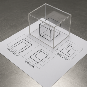
The primary method used is orthographic projection, which represents a 3D object using a series of 2D views.
Picture the part inside a transparent “glass box.” The image of the part is projected onto the front, top, and side panels of the box. When you unfold the box, you get the standard multi-view layout you see on a drawing.
First Angle vs Third Angle Projection Standards
This is one of the most critical details for a buyer to check. Misinterpreting the projection standard can result in a mirrored part—a costly and entirely avoidable manufacturing error. Understanding the difference is fundamental to working across international technical drawing standards (ISO vs ASME).
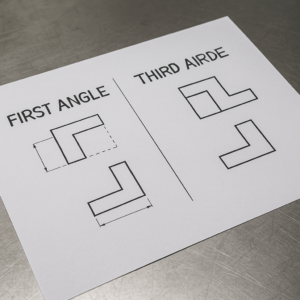
- Third-Angle Projection (ASME Standard): Used primarily in the US, Canada, and Japan. The layout is intuitive: the top view is located above the front view, and the right-side view is to the right.
- First-Angle Projection (ISO Standard): The standard in Europe and most of Asia. The layout is opposite: the top view is below the front view, and the right-side view is to the left.
Every professional drawing contains a projection symbol in the title block. Verifying this symbol is the first step in avoiding cross-regional misinterpretation.
When working with international suppliers, verifying the projection method is essential. A misunderstanding between first-angle and third-angle projection can result in mirrored parts that do not assemble correctly.
Because different regions follow different drawing standards, confirming the projection symbol early in the quoting or review process helps prevent manufacturing errors and delays.
The “Alphabet” of Lines in Metal Fabrication
Different line types have specific meanings that communicate critical information to the machinist.
- Visible Lines: Thick, solid lines showing the part’s visible edges.
- Hidden Lines: Dashed lines indicating features that are not visible from that view, such as internal holes or steps on the back of the part.
- Center Lines: A long-short dash pattern used to locate the exact center of holes and symmetrical features.
How to Review a Metal Part Drawing Before Manufacturing
Reading a drawing is not passive. For a procurement professional, it’s an active audit for manufacturability, cost drivers, and quality assurance. This 5-step process helps you evaluate a drawing before you even send out an RFQ — making it a key part of any drawing-based RFQ review.
Step 1: Start at the Control Center—The Title Block and Notes
The most critical information is often in the corners of the drawing, not the main views. This is where the overarching rules are defined.
- The Title Block: This is the part’s passport, consolidating its core production parameters. Quickly locate the Material Specification (e.g., SUS304, AL6061-T6), the General Tolerances, and the Projection Symbol. These details are foundational to your quote and supplier evaluation.
- Technical Notes: This section often contains key cost and process indicators. Look for requirements like heat treatment, specific deburring instructions, or required finishing processes like anodizing or powder coating. These notes may have a more significant impact on cost than geometry itself.
Step 2: Build the 3D Mental Model—Correlate Views
Now correlate the primary views (front, top, side) to mentally reconstruct the part. Use view alignment to interpret how features interconnect. A circle in one view appearing as dashed lines in another defines a hole’s depth—crucial for understanding machining paths and complexity.
Step 3: Look Inside and Zoom In—Deciphering Specialized Views
Specialized views clarify complex or hidden features, minimizing ambiguity.
- Sectional Views: An imaginary cut through the part to reveal internal features clearly. Essential for understanding complex internal geometries without visual clutter.
- Detail Views: A magnified focus on intricate areas, like an O-ring groove or tight corner. These ensure dimensioning clarity for small features.
- Auxiliary Views: The only way to show inclined surfaces in true size and shape. Critical for accurately machining features on angled planes.
Step 4: The Art of Precision—Interpreting Dimensions and Tolerances
Dimensions define size; tolerances define manufacturability. This is where attention to detail impacts production cost.
Understand the difference between a basic and a toleranced dimension. Every dimension requires a tolerance—directly stated or specified in the general notes. Tight tolerances (e.g., ±0.05mm) are significantly more expensive than broader ones (e.g., ±0.2mm). Evaluating these helps you spot unnecessary complexity and apply dimensioning and tolerancing best practices.
Step 5: Decode “Special Instructions”—Surface Finish and Welding
These symbols govern non-dimensional specifications that influence both cost and function.
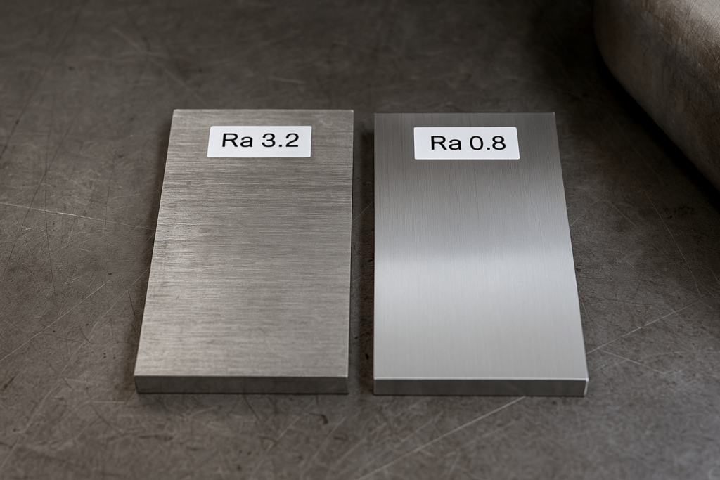
- Surface Finish: Defined by Ra (Roughness Average). Lower Ra = smoother finish. Achieving it may require grinding or polishing—secondary steps that raise unit cost. Refer to surface finish standards for consistent quoting.
- Welding Symbols: For fabricated assemblies, these define weld type, size, and location.
GD&T: Function-Driven Tolerancing for Higher Quality
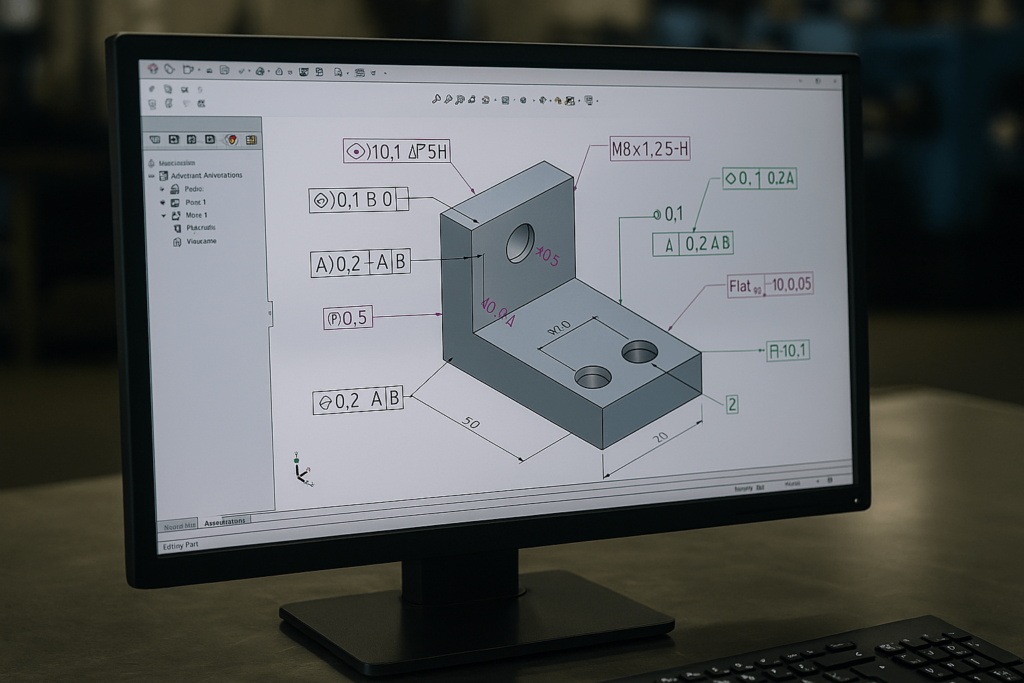
Geometric Dimensioning and Tolerancing (GD&T) is a precise language that extends beyond simple ± tolerances to define part form, orientation, and location.
Why GD&T Matters for Buyers
Traditional ± tolerancing defines a square zone. GD&T can define a circular zone—57% larger—offering greater manufacturability without sacrificing intent.
For buyers, GD&T improves quality control and cost optimization. Suppliers who understand it can provide smarter quotes and better output consistency. This makes it essential in any supplier drawing evaluation guide.
The Cornerstones of GD&T
- Datums: Theoretically perfect references—points, lines, or planes—that define how a part should be measured and assembled.
- Feature Control Frame: A rectangular box that houses the geometric tolerance symbol, value, and related datums.
- 14 Geometric Characteristics: Control shape, orientation, and location—including Flatness, Cylindricity, True Position, and Runout—ensuring the part performs as intended.
Types of Engineering Drawings in Product Development
A complete product involves more than one drawing—it includes a system of technical documentation.
- Detail Drawing: Specifies how to machine a single component.
- Assembly Drawing: Illustrates how components fit together, usually including a Bill of Materials (BOM) with item numbers, materials, and quantities.
- Exploded View: Shows disassembled parts spatially, revealing how they interconnect—useful for both manufacturing and QC teams.
Future Trends in Engineering Documentation
- Model-Based Definition (MBD): Consolidates all Product Manufacturing Information (PMI) directly within the 3D CAD model—minimizing errors from file mismatches.
- Digital Twin: A dynamic virtual copy of a physical product that reflects real-time performance and lifecycle data. Valuable for predictive maintenance and process improvement.
Despite these trends, the 2D drawing remains the industry’s binding contract, offering unmatched clarity, accessibility, and regulatory compliance.
Conclusion: The Common Language of Quality and Partnership
Engineering drawings remain one of the most important tools for communicating manufacturing requirements. They define dimensions, tolerances, materials, and finishing processes in a standardized format that can be interpreted consistently across global supply chains.
By understanding how to read and evaluate these drawings, engineers and sourcing teams can better identify potential manufacturing challenges and ensure that parts meet the required specifications.
Even as digital technologies such as model-based definition continue to develop, the engineering drawing remains a fundamental reference for precision manufacturing.
Last updated: March 2026
