The Real Flange Problem Isn’t in the Formula — It’s in the Factory
For global procurement teams sourcing precision sheet metal parts, speed and consistency are everything. Yet too often, seemingly correct designs lead to production delays and unnecessary cost.
The culprit? A flange formula that doesn’t reflect manufacturing realities.
A finished CAD file may suggest production readiness. But our 26 years of experience at YISHANG prove otherwise — we’ve seen flanges fail due to cracking, warping, or critical tolerance deviations.
The formula might appear sound in CAD software. But real-world production often introduces variability — from tooling conditions to material properties — that can cause it to fall short.
In high-volume procurement, even a small scrap rate can impact cost and timelines. That’s why we prioritize identifying flange-related risks early in the process.
The more design aligns with real tooling and forming behavior, the more predictable and scalable your results.
Why Standard Flange Formulas Can’t Be Trusted Blindly
The standard formula — Minimum Flange Height = 4 × Thickness + Bend Radius — provides a useful baseline. But it assumes ideal conditions between design input and tooling execution. In production, those conditions often fluctuate.
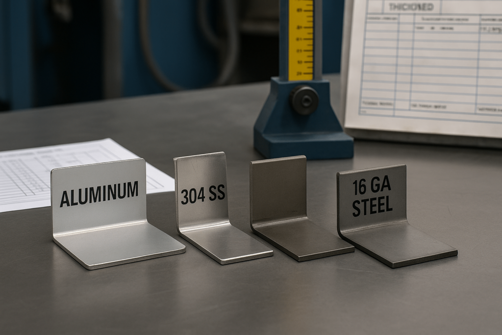
Most metal sheet manufacturers work with varying material properties, changing tool conditions, and inconsistent springback. K-factors, for example, can deviate depending on thickness, tooling, and bend method. A shift from 0.33 to 0.42 can create dimensional mismatches of over 1mm.
Table 1: Flange Length Error vs. K-Factor Deviation
| Assumed K-Factor | Actual K-Factor | Bend Angle | Flange Length Error (mm) |
|---|---|---|---|
| 0.33 | 0.42 | 90° | +1.2 mm |
| 0.40 | 0.35 | 90° | -0.9 mm |
| 0.38 | 0.30 | 135° | -1.5 mm |
These discrepancies might be negligible in simple round sheet metal shapes, but for structural assemblies or laser cut metal panels, a millimeter matters. Our team we rely on validated production data to adjust flange dimensions, rather than depending solely on CAD-based formulas.
Buyers are encouraged to verify whether their vendor’s flange calculations reflect actual forming results and not just theoretical inputs.
What 26 Years of Making Flanges Taught Us About What Actually Works
From enclosures to bent sheet metal brackets, we’ve produced flanges in all materials and scales. Over time, our team has refined process-proven guidelines that reduce risk.
Minimum Flange Height ≥ 2.5 × Material Thickness + Actual Bend Radius
This formula accommodates secure material grip during forming, especially with thicker materials like 12 gauge sheet metal. Undersized flanges often result in tearing, slippage, or misshaped bends.
Hole Distance from Bend ≥ 2.5 × Thickness + Internal Radius
Proper spacing helps avoid stress fractures, particularly in figur sheet metal or when mounting holes are close to bends. In one case, applying this rule improved a client’s pass rate by 3%.
Material-specific behaviors also matter. For example, in anodized aluminum sheet metal, springback can exceed 6°, which requires radius compensation in tooling selection. Instead of relying on general charts, we log machine-specific outcomes to consistently maintain ±0.2mm flange accuracy batch over batch.

From Design to Production: How to Make Your Flange Actually Work
Even if a flange checks the formula box, it may not match your vendor’s real-world tooling. A typical error: designing a 6mm flange on 2mm stock with a 5mm V-die. That flange won’t form properly — it’s a setup conflict, not a math issue.
Our team we identify these mismatches early. If secondary trimming or a multi-pass approach is required, we incorporate that into the production flow — avoiding last-minute surprises. For complex shapes, we sometimes suggest design tweaks, such as bend reliefs or altering the bend sequence.
A recent project involving a bracket made of 16 gauge sheet metal suffered from edge distortion due to springback. By switching to air bending sheet metal and slightly enlarging the bend radius, the issue was resolved—scrap rate dropped to zero across a full production run of 2,000 units. Flanges that appear correct on drawings require a full production-level reality check — including on-machine validation — to confirm they maintain dimensional integrity and form without compromise.
How We Validate a Flange Before It Becomes a Problem
Our validation protocol bridges the gap between design and production. Before scaling any order, we prototype flange sections using the same material, die set, and bend method that will be used in the final run.
We test:
Actual vs. expected bend angles
Final flange height
Springback variance
Instead of relying solely on standard bend radius sheet metal charts, we log real-time data by batch and machine. Environmental variables like temperature and humidity are tracked as well.
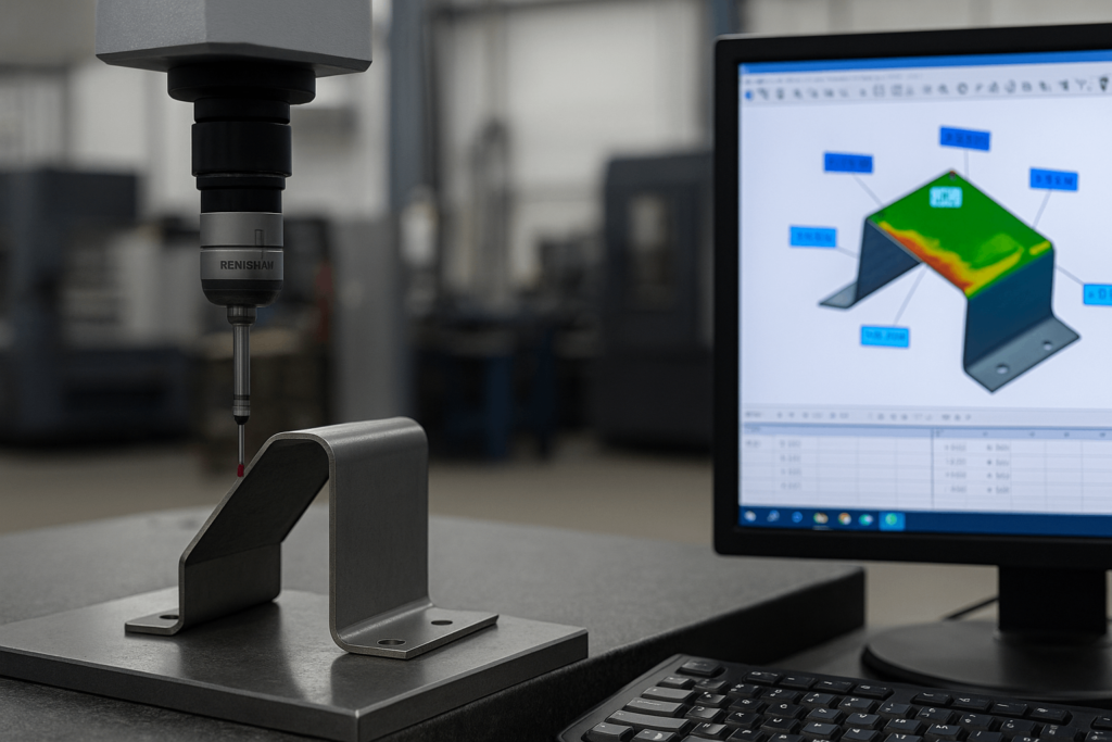
Our inspections use calibrated CMMs and ISO-aligned visual standards. If deviations exceed 1° or 0.5mm, the job is paused and realigned. This ensures predictable outcomes for buyers — with rework rates reduced by over 15% through early validation of flange geometry and bend accuracy.

Case: One Flange Saved an Entire Project
A North American customer submitted a 3,000-unit job with over 30 flanges per control box. Despite using widely accepted formulas, 40% of parts failed during forming due to undersized flanges and ignored springback.
Our trial run caught the issue. The flange dimensions were incompatible with the available V-die geometry, and the CAD software did not factor in the material’s springback behavior.
We revised the flat layout using our internal bend tables, increased the flange height by 1.5mm, and introduced a post-form trim step. The result: 100% pass rate and on-time delivery. The customer has since standardized pre-checks with us for all spec sheet metal orders, preventing future errors and optimizing procurement timelines.
Download Our Flange Reality Checklist — Free
Before placing your next order, ask:
✅ Does your flange height match your fabricator’s tool setup?
✅ Are holes spaced far enough from bends to avoid stress?
✅ Has springback been tested in the actual forming setup?
✅ Is your bend table based on validated production data?

