
Table of Contents
隐藏
Cutting tin metal looks like a basic fabrication step, but it carries real weight in industrial sourcing. Buyers who handle sheet‑metal procurement know that the cut quality affects more than appearance. It influences flatness, accuracy, assembly speed, and the long‑term behavior of the final product. When a supplier controls these variables well, production flows smoothly. When they do not, delays, rework, and quality disputes appear quickly.
Many professionals search terms like how to cut tin metal, best way to cut sheet metal, or how to cut thin sheet metal because they want a clearer understanding of what good cutting looks like at scale. The goal is not to learn hobby techniques—it is to evaluate whether a supplier has stable processes and whether their capabilities match the needs of display racks, enclosures, vending assemblies, or other thin‑metal products.
This article provides that context. It explains how thin tin‑metal behaves during cutting, how different methods influence distortion, and how these technical details translate into procurement‑level decisions. The goal is simple: help buyers judge cutting quality with confidence, reduce sourcing risk, and choose suppliers who can deliver consistent results.

Tighter tolerances correlate with guided cutting and automation. Buyers can reduce risk by asking suppliers how they control tolerances and how often machines are calibrated. The answers often reveal whether the supplier planned the workflow around real production demands.
Quick answer: best ways to cut tin and thin sheet metal
For small quantities or simple shapes, tin snips or aviation snips offer the easiest way to cut tin or thin steel sheet. They work well for brackets or low‑precision parts. For larger panels that must stay flat, electric shears or nibblers provide smoother edges with less distortion. When a project requires accuracy and repeatability—such as enclosure panels or display fixtures—the most reliable choice is CNC shearing, punching, or laser cutting. These methods control sheet movement, improve edge consistency, and hold tighter tolerances.Understanding Thin Tin‑Metal Behavior During Cutting
Why Tin Sheet Reacts So Quickly—and Why This Matters
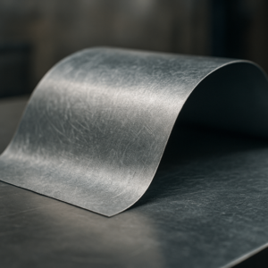
Thin tin‑coated steel responds immediately when a blade touches it. The sheet flexes before it fractures, and this brief movement shapes the entire outcome of the cut. If the sheet is not supported, that movement becomes curl, twist, or surface marks. Many buyers describe this effect as the material “running away” from the tool when searching for the easiest way to cut tin or easy way to cut tin. In a factory setting, this same behavior can produce large variations in quality if not controlled. For procurement teams, this sensitivity explains why suppliers using identical material can produce very different results. A supplier that stabilizes the sheet, manages progression, and protects the usable side delivers flatter and more accurate parts. A supplier relying on force instead of control often produces components with unpredictable warping and inconsistent assembly fit. These differences directly affect lead times, scrap rates, and downstream labor. The same principles apply to galvanized steel and other thin sheet metals. The metal’s responsiveness is not an excuse for poor results—it is a factor that skilled factories plan for. When buyers understand this behavior, they can interpret real defects instead of assuming distortion is unavoidable. This leads to better evaluation of cutting samples and clearer expectations in RFQs.
The Three Primary Forces Behind Warping
Warping occurs because three forces act on thin sheet at the same time. The first is lateral force from the operator or cutting head. Even a small sideways push bends thin metal. The second is compression between the blades before separation. Too much compression distorts the sheet. The third is internal tension from rolling, storage, and handling. When a cut releases that tension, the sheet may lift or curl along predictable directions. Thin metal amplifies these forces. Minor changes in angle or hand pressure result in visible differences in the cut. This explains why people searching how do you cut tin or how can I cut metal often see inconsistent results. At scale, these same inconsistencies translate into variation between parts and higher rework rates. Professional factories avoid this by controlling every stage of the cut. They support the sheet at key points, use partial blade closures to avoid compression spikes, and guide the waste side so it curls away from the usable part. When buyers recognize the forces that create warping, they can read curling, drift, or marks as indicators of process control rather than random defects.How Material Behavior Knowledge Helps Supplier Evaluation
Understanding thin‑metal behavior gives procurement teams a clearer way to judge cutting capability. Some distortion is natural, but recurring patterns—such as repeated burr types, consistent uplift, or predictable drift—point to process weaknesses rather than material limits. When a factory consistently produces flat and clean parts at the same thickness, it signals mature control over thin‑sheet behavior. This perspective helps buyers make more precise comparisons. Instead of focusing only on price or assuming all suppliers face the same technical limits, they can connect sample quality to actual process capability. This reduces sourcing risk, improves long‑term stability, and increases the chance of selecting suppliers who can meet the needs of display systems, vending assemblies, and enclosure parts.Choosing Cutting Methods Based on Technical Requirements and Procurement Priorities
Straight Cuts for Panels, Brackets, and High‑Volume Parts
Straight cuts appear simple, but they influence most thin‑sheet products: enclosure panels, display‑rack parts, trims, and brackets. The best results come from tools that guide the sheet and limit movement. Bench shears, guillotine cutters, and slitting lines all work well when supported by stable setups. Buyers can evaluate straight‑cut quality with quick checks. Wavy edges signal that the sheet shifted during cutting. Squeeze marks often indicate excessive compression. Angle variation between pieces from the same batch points to unstable setups or tool wear. These issues increase assembly time and add pressure to downstream processes. Factories that invest in guided systems produce cleaner edges and more consistent flats. Their long parts stay straighter, reducing corrective bending and improving fit during assembly. When buyers ask how a supplier supports long cuts, the answers reveal whether repeatability is part of their workflow or an afterthought.
Curved and Complex Shapes Where Stress Builds Up
Curved paths, small openings, and interior contours introduce extra stress. These shapes change the way metal carries force, and thin tin‑sheet reacts quickly. Manual snips can handle gentle curves, but they depend heavily on operator control. Tight radii, narrow slots, or interior cutouts often push hand tools beyond their limit. This is why many buyers researching the best way to cut metal or how to cut steel sheet metal for complex profiles end up specifying CNC punching or laser cutting. Automated systems control the sheet, manage heat or pressure consistently, and keep geometry stable across large batches. When comparing quotes for complex parts, procurement teams should confirm that the proposed method matches the drawing’s real demands. A simple‑looking shape can hide stress‑heavy transitions. If a supplier chooses a manual method for geometry that requires automation, accuracy and consistency will suffer at volume.Matching Cutting Methods to Tolerance Expectations
Different cutting methods support different tolerances. Misalignment between expectations and technique is a common cause of disputes. A supplier relying on hand snips cannot match the stability of a CNC‑equipped factory, especially on tight‑tolerance brackets or enclosure panels. Below is a simplified comparison used in industrial sourcing:| Cutting Method | Thickness Range (mm) | Typical Tolerance (mm) | Consistency Level | Common Use |
|---|---|---|---|---|
| Snips / Manual | 0.3–0.6 | ±0.5–1.0 | Low–Medium | Simple shapes, small quantities |
| Bench Shear | 0.4–1.0 | ±0.3–0.5 | Medium | Straight cuts, small/medium batches |
| Electric Shear / Nibbler | 0.4–1.2 | ±0.3–0.5 | Medium–High | Repetitive outlines, moderate volumes |
| CNC / Laser | 0.3–2.0 | ±0.1–0.2 | Very High | Complex, precision, high‑volume parts |
Tools Overview: From Snips to CNC Laser
Each tool fits a different stage of production. For small, simple parts, tin snips and aviation snips are still the easiest way to cut tin or thin steel sheet. They suit low quantities where some variation is acceptable. Electric shears and nibblers offer smoother edges and faster throughput. They spread force more evenly and reduce distortion. Many factories use them for repetitive outlines, especially when buyers need moderate volumes of thin‑sheet components. For precision assemblies—such as vending interfaces, enclosure fronts, or detailed bracket sets—CNC shearing, punching, or laser cutting delivers the best stability. These automated methods align with searches like how to cut thin steel sheet and how to cut thin sheet metal at scale. They help factories maintain tight tolerances, protect geometry, and keep edges consistent across large orders.Factory‑Logic Cutting: Why Professional Operations Deliver More Consistent Results
Factory‑Logic Cutting: Why Professional Operations Deliver More Consistent ResultsStability and Setup: The Foundation of Cutting Quality
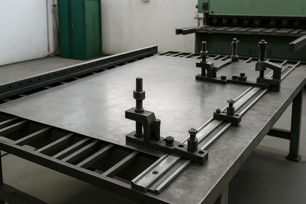
In professional fabrication, good cutting is built on good setups. Stability matters more than raw strength. Factories that treat cutting as a controlled process rather than a manual task invest in flat work surfaces, reliable clamping, anti‑slip mats, and fixtures that prevent sheet movement. These elements ensure the sheet stays exactly where it should when the blade engages. For thin tin‑metal, even minor sliding or lifting magnifies into visible defects. If sample parts from a supplier show uneven flatness, inconsistent edge conditions, or small shifts in hole position that do not match the drawing, it often means the sheet was not properly stabilized. Buyers can detect such problems with basic checks: placing a part on a flat surface, observing whether it rocks, or comparing several pieces side by side to see if cut lines truly match. Suppliers with strong setup discipline document their cutting configurations, reuse proven fixture designs, and train operators to follow defined procedures. This approach turns cutting into a repeatable system. For procurement teams focused on long‑term partnerships, evidence of such stability is a reassuring sign that the supplier can support future design changes or volume increases without losing control.
Controlled Progression to Minimize Stress and Distortion
Progression—the way a cut advances—is just as important as the type of tool. Professional operators rarely close manual snips fully on thin sheet because a full close compresses the material excessively and creates a visible pinch at the end of each stroke. Instead, they use short, overlapping cuts, advancing gradually. In automated systems, similar logic applies as feed rates and stroke settings are tuned to avoid overstressing the sheet. From a procurement perspective, the results of poor progression are easy to recognize. Edges may appear serrated, with repeating small deformations along the cut, or burr height may vary along the same edge. Inconsistent progression also leads to variations between pieces that were theoretically cut using the same method. During supplier evaluation, buyers can ask not only what tool is used but how it is used. A supplier able to explain their approach to progression—whether manual or automated—usually has a more mature understanding of cutting as a controlled operation rather than a simple separation step.Managing the Waste Side to Protect the Usable Part
In thin‑metal cutting, the waste side naturally wants to move. Professional cutters design their process so the waste is allowed to curl or drop away in a controlled manner while the usable part remains as flat as possible. If the waste side is restrained incorrectly or allowed to twist unpredictably, it will pull the usable side out of shape. This principle is especially important for long cuts and narrow strips, such as those used in framing or trims for display racks and housings. When assessing samples, buyers can look at whether the usable sections show twist or bow that mirrors the path of the waste. If that pattern appears consistently, it suggests that the supplier’s cutting strategy does not sufficiently protect the good material. A supplier who understands waste‑side management can usually show fixtures, clamps, or guides designed specifically for this purpose. This is another indicator of process maturity and is directly tied to the flatness and dimensional stability of the delivered parts.Micro‑Adjustments for Line Accuracy and Dimensional Stability
Thin metal rarely behaves perfectly predictably throughout a cut. Tension can change as the sheet is opened, and local stiffness may vary near bends, edges, or previous cut lines. Skilled operators account for this by making micro‑adjustments: slight changes in cutting angle, minor corrections to hand position, and small repositioning of supports mid‑cut. For buyers, the evidence of good micro‑adjustment is consistent edge alignment and low variation between nominally identical parts. If some pieces fit assembly fixtures well while others from the same batch need force or adjustment, it may indicate inconsistent micro‑control during cutting. This kind of variation can be especially disruptive in high‑volume assembly environments, where speed and repeatable fit are critical. Suppliers who take micro‑adjustments seriously often support operators with guides, markings, and training rather than expecting each person to “feel it out” individually. For procurement teams, this kind of support structure shows that the factory is managing human variation instead of ignoring it.Troubleshooting Visible Defects: A Practical Guide for Assessing Samples
Curling or Uplift: Signals of Stability and Progression Issues
Curling and uplift along cut edges are common but revealing indicators in tin‑metal fabrication. When a sheet curls predictably and uniformly, it usually reflects normal stress release. However, when curl appears irregular, inconsistent, or varies noticeably between pieces within the same batch, it suggests that the cutting setup lacked sufficient stabilization. This often occurs when operators rely too heavily on force or when fixtures fail to restrict sheet movement at critical points. For procurement teams assessing samples, curl patterns help identify whether the supplier understands sheet‑behavior control. Suppliers with mature processes stabilize sheets differently based on part geometry—long trims, narrow strips, or interior cutouts each require tailored support. When a supplier can explain these setup variations clearly, buyers gain confidence that future production will maintain consistent flatness even when designs evolve.Burrs, Ragged Edges, and Micro‑Tears: What They Indicate
Burrs and ragged edges influence downstream efficiency more than many buyers realize. High burrs increase deburring labor, affect coating adhesion, and disrupt assembly alignment in enclosures, vending components, and display structures. Evaluating burr quality gives buyers insight into tool condition, operator consistency, and maintenance routines. Short, even burrs generally indicate correct blade clearance and stable progression. Long, fibrous burrs often point to dull tooling or excessive compression. Micro‑tears—small fractures visible on the underside—signal mismatched tooling clearance or aggressive stroke settings. These defects reveal whether suppliers maintain proper tooling standards and how they monitor quality during long production runs.Drifting Lines: Alignment and Visibility Problems
Cut‑line drift occurs when the cutting path slowly deviates from the intended line. For structural components or enclosure parts, even slight drift can disrupt fit. Drift is usually traced to inadequate visibility of markings, missing guiding fixtures, or weak operator control. When reviewing samples, procurement teams should compare several identical components. If each piece shows subtle variations in angle or contour, it means the supplier relies excessively on manual guidance. Factories that use physical stoppers, laser guides, or programmed CNC paths typically achieve far higher consistency, especially for repetitive outlines.Snagging Marks and Stress Cracks: Warning Signs for Critical Parts
Snagging occurs when cutting tools drag or catch on thin sheet metal, leaving dents, stretch marks, or micro‑cracks. These defects matter greatly for parts that will undergo further forming or vibration exposure, such as structural brackets or inner frames of vending machines. Stress cracks weaken long‑term durability and often originate from outdated tooling, incorrect clearances, or improper progression. When procurement teams encounter snagging or cracking, they should confirm the supplier’s tooling maintenance intervals and clearance‑adjustment practices.Safety and Edge Handling When Cutting Tin and Thin Sheet Metal
Thin tin‑metal often produces sharp burrs and thin fragments during cutting, which increases handling risks. Factories with strong safety culture tend to produce cleaner, safer edges because their processes emphasize burr control, blade maintenance, and post‑cut handling checks. For procurement teams, edges that are consistently safe to touch signal well‑maintained processes. This matters for product lines where installers or end users interact with exposed metal—display rack joints, vending machine access points, or enclosure doors. Smooth edges reduce warranty claims, improve perceived product quality, and lower assembly injury risks.Advanced Cutting Systems for High‑Precision and High‑Volume Production
Stability Systems and Tooling Integration in Modern Factories
Advanced fabrication relies on engineered stability rather than reactive correction. Modern factories integrate modular clamping systems, guided support rails, anti‑vibration beds, and dedicated fixtures built around recurring product families—such as display racks, vending assemblies, and enclosure frames. These systems reduce sheet drift, maintain reference alignment, and ensure that each piece begins and ends the cut from consistent datum points. For procurement teams, this engineered stability is a strong signal that a supplier is not simply producing parts but managing a controlled workflow. When suppliers can demonstrate repeatable fixture usage, consistent clamping logic, and documented setup sheets, buyers gain assurance that quality will remain stable as volumes increase or product lines expand.Precision Cutting for Enclosures, Vending Assemblies, and Display Structures
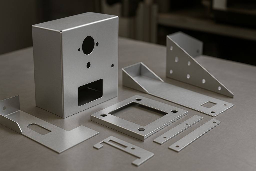
Product categories with complex assemblies require more than clean edges—they require dimensional intent. Enclosures depend on alignment across door panels, internal brackets, and ventilation cutouts. Vending assemblies require consistent joint spacing and burr‑free openings to ensure smooth mechanical movement. Display structures must maintain parallelism and clean contours to achieve proper visual presentation. CNC shearing, laser cutting, and CNC punching address these needs by managing progression, blade path, and thermal or mechanical stress in ways manual tools cannot. These systems generate predictable burr height, repeatable contours, and stable geometry across large batches. Procurement teams can evaluate precision by comparing multiple samples from the same batch and checking how consistently they fit into assembly fixtures. High‑quality suppliers demonstrate uniformity not by chance but by automated control.
