
A lathe operation uses controlled relative motion between a rotating workpiece and a cutting tool. By moving the tool along or across the workpiece, the process can create end faces, cylindrical diameters, steps, grooves, chamfers, and threads.
Successful turning depends on more than tool movement. The operator or programmer must review the drawing, secure the stock, establish offsets, select suitable cutting parameters, check clearance, control chips, and verify the stationary part after machining.
How a Lathe Controls the Workpiece and Cutting Tool
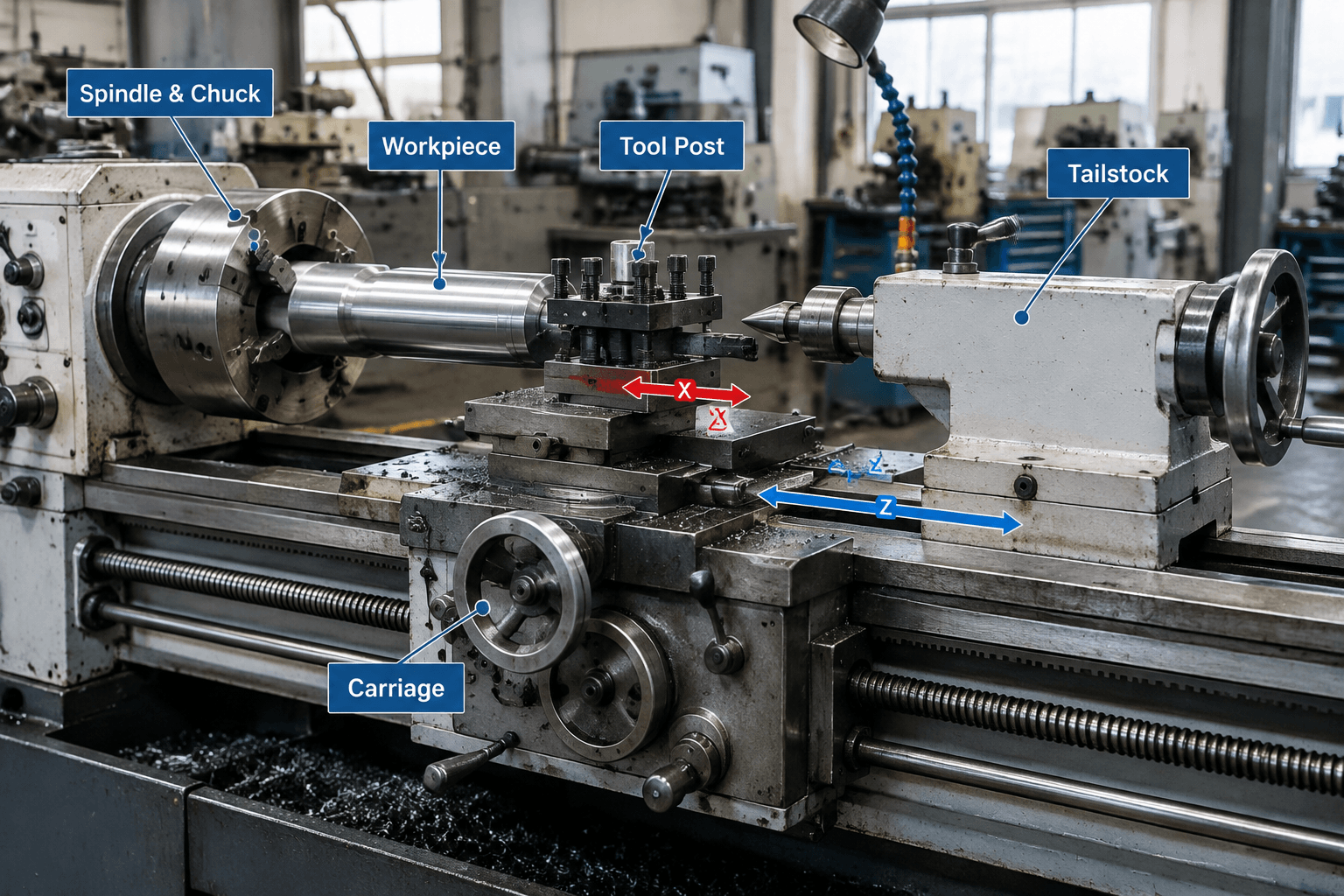
In conventional turning, the spindle rotates the workpiece while a non-rotating cutting tool feeds relative to it. Movement parallel to the spindle centerline is commonly described as the Z direction. Radial movement toward or away from the centerline is the X direction. Coordinating these motions changes the part’s length, diameter, or profile.
| Lathe component | Primary function |
|---|---|
| Bed | Provides the structural base and aligned guideways for the machine’s moving units. |
| Headstock and spindle | House and drive the rotating spindle that transmits motion to the workpiece. |
| Chuck | Grips the stock or part. Jaw type, condition, gripping length, and clamping method affect security and concentricity. |
| Carriage | Supports and moves the cutting tool along the machine’s working axes on a manual lathe. |
| Tool post | Holds and positions the cutting tool. CNC machines commonly use a turret or another indexed toolholding arrangement. |
| Tailstock | Can support long workpieces or hold a center or axial tool when the machine design and setup permit. |
On a manual lathe, an operator controls tool position with handwheels and machine feeds. A CNC lathe follows programmed coordinates, tool offsets, spindle commands, and feed commands. A turning center may add features such as a tool turret, sub-spindle, live tooling, or extra axes, but these are configuration-dependent. CNC control improves automation and consistency of commanded movement; it does not by itself guarantee accuracy, economy, or short cycle times.
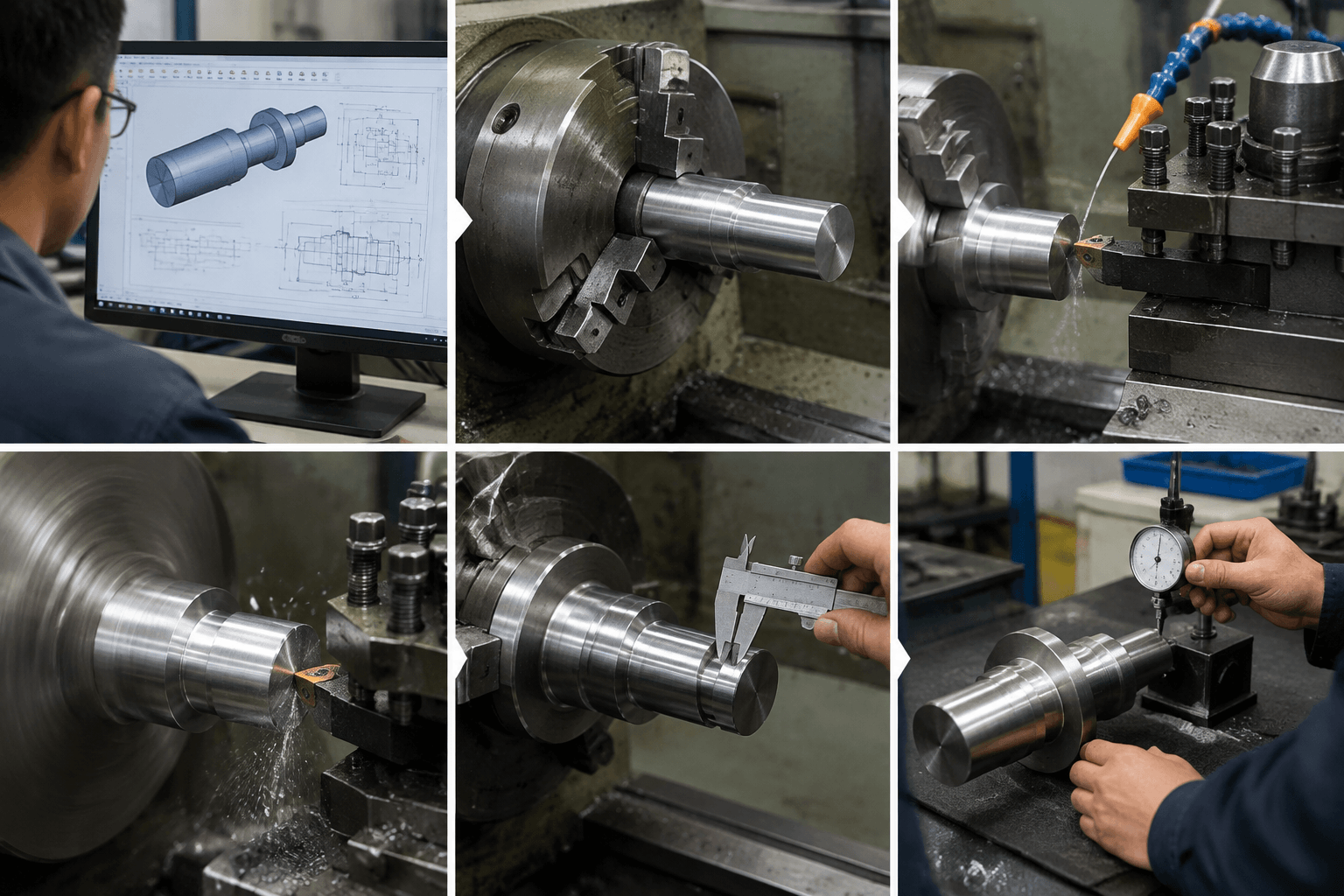
Operating Sequence: From Drawing Review to Verification
- Review the drawing or CAD model. Identify datums, finished diameters, overall lengths, shoulders, grooves, threads, surface requirements, and non-rotational features. Determine which surfaces are accessible in each setup and whether the part must be reversed.
- Select and prepare the stock. Confirm the material grade and choose bar, tube, casting, or prepared blank with enough machining allowance. Cut or prepare the blank as required, remove burrs that could affect handling or seating, and clean the gripping and locating surfaces. Excess allowance adds cutting, while insufficient stock can leave an incomplete surface.
- Plan workholding. Choose suitable chuck jaws, a collet, a fixture, or supported holding according to the stock shape and operation. Minimize unsupported stick-out while preserving tool access. Delicate or previously finished surfaces may need protective or purpose-made gripping arrangements.
- Install and align tools. Select roughing, finishing, grooving, threading, or other tools as required. Check cutting-edge orientation, tool height, holder rigidity, and clearance from jaws, fixtures, and adjacent shoulders.
- Establish references and offsets. A manual setup requires clear datum and dial references. A CNC setup requires the work coordinate, tool geometry offsets, and appropriate wear offsets. The program defines the intended path, but the physical setup determines where that path occurs.
- Perform a clearance check. Confirm chuck security, jaw engagement, tool reach, spindle direction, and safe approach positions. For CNC operation, a controlled dry run, simulation, or single-block check may be appropriate depending on the machine and procedure.
- Machine the part. Roughing passes remove the main allowance under a stable cutting load. Finishing passes then target final size and surface condition. Chips, heat, vibration, and edge wear should be monitored throughout the operation.
- Stop and verify. Bring the spindle to a complete stop before measuring. Inspection is a separate verification step using suitable instruments for diameters, lengths, grooves, threads, runout, and other specified characteristics. Record or respond to the result according to the production control plan.
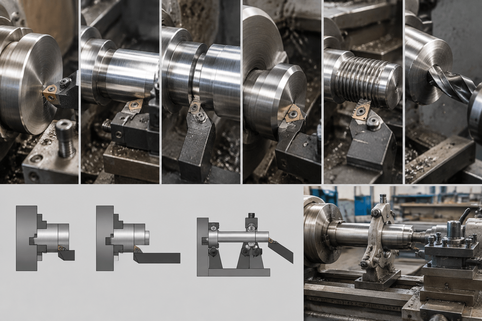
Lathe Operation Planning Matrix: Feature, Tool, Motion, and Checks
A drawing can be translated into a sequence by connecting each feature with its cutting direction, tool access, workholding risk, and verification method.
| Feature | Operation and tool | Typical motion | Setup and verification focus |
|---|---|---|---|
| Flat end surface | Facing with a facing or general turning tool | Radial movement across the end | Jaw clearance, finished length, and face condition |
| Uniform outside diameter | Longitudinal turning with an external turning tool | Axial movement along Z after setting depth in X | Rigidity, diameter, cylindricity, and surface requirement |
| Multiple diameters | Step turning | Combined axial and radial positioning | Shoulder access, step diameters, and shoulder locations |
| Narrow recess | Grooving with a width-appropriate grooving tool | Primarily radial entry | Tool overhang, chip evacuation, groove width, depth, and location |
| Edge break | Chamfering with a chamfer or turning tool | Coordinated X-Z movement or formed-tool entry | Adjacent feature clearance and specified chamfer size |
| Helical profile | Threading with an internal or external threading tool | Feed synchronized with spindle rotation | Pitch, form, diameter, tool alignment, and thread fit |
| Axial hole or enlarged bore | Drilling or boring where supported | Axial tool feed or internal turning | Machine arrangement, tool support, chip removal, bore size, and depth |
Cross-holes, flats, off-center holes, and other transverse features are not produced by standard two-axis turning alone. They may require a turning center equipped with suitable live tooling and axes, or a separate milling or drilling operation. Parts combining turned and non-rotational geometry may need a broader CNC machining route.
Choosing Speed, Feed, Depth of Cut, and Tool Geometry
Cutting parameters work as a system. Cutting speed influences heat generation and edge life. Feed affects chip thickness, cutting force, productivity, and the resulting surface. Depth of cut determines how much material the tool engages. Tool geometry affects cutting pressure, chip formation, edge strength, and access to the feature.
Increasing one variable can change the acceptable range of the others. A deep cut with an aggressive feed may overload a slender part or weak setup. A worn tool can generate additional heat, dimensional drift, poor chip control, and an inconsistent finish even when the programmed values have not changed.
| Material group | Planning considerations |
|---|---|
| Aluminum alloys | Sharp cutting edges and effective chip evacuation help limit built-up material. Actual settings depend on alloy, temper, tool coating, and rigidity. |
| Carbon steels | Strength, hardness, and heat treatment affect cutting load, chip form, and tool selection. A general material label is not enough to set parameters. |
| Stainless steels | Work hardening, heat concentration, and difficult chip behavior may require controlled engagement, suitable geometry, and close tool-condition monitoring. |
| Copper and copper alloys | Machinability varies substantially by alloy. Ductile grades can create long chips or built-up material, while free-machining grades behave differently. |
| Titanium alloys | Heat at the cutting zone, cutting forces, and edge wear require conservative process planning and rigid workholding. |
| Cast iron | Grade and microstructure influence abrasiveness, edge wear, dust, and chip behavior. Tool and machine protection should suit the material. |
| Engineering plastics | Sharp-edged tools and parameters selected to control heat help reduce softening, melting, and dimensional change. Clamping must avoid distortion. |
Final parameters should be validated for the specific material grade, insert or tool material, machine condition, coolant strategy, workholding, feature geometry, and required result. Supplier data and controlled trial cuts provide a starting point, not a universal setting.
What Causes Dimensional and Repeatability Variation?
The same manual settings or CNC program can produce different results when the physical system changes. Workholding is a frequent source. Worn or contaminated jaws may seat parts differently, limited gripping length can reduce security, and excessive stick-out makes a part more susceptible to deflection or chatter. Tailstock or other support may help some long parts, but support method and force must suit the geometry.
| Setup risk | Possible effect | Control approach |
|---|---|---|
| Part not seated consistently | Length or runout variation | Clean locating surfaces and define a repeatable loading method |
| Excessive stick-out | Vibration, taper, deflection, or poor finish | Reduce overhang or introduce suitable support |
| Incorrect tool alignment or offset | Size, profile, or thread-form error | Verify setup references and offsets before production |
| Progressive tool wear | Dimensional drift and changing surface condition | Inspect the edge and manage replacement or wear compensation |
| Chip accumulation | Surface damage, recutting, heat, or tool interference | Plan chip flow and stop safely if manual removal is necessary |
| Thermal change | Changing dimensions during a run | Use a stable process and verify parts at appropriate intervals |
First-piece inspection confirms whether the setup produces the intended result before a series continues. In-process inspection then detects drift. Neither is part of the cutting action itself. Repeatability comes from stable locating surfaces, controlled clamping, reliable offsets, monitored tools, suitable measurement, and a documented response to variation—not from CNC programming alone.
Frequently Asked Questions
What are the main parts of a lathe?
The principal parts are the bed, headstock and spindle, chuck, carriage, tool post or turret, and tailstock. Together they support the machine, rotate and hold the workpiece, position the cutting tool, and provide support or axial-tool holding where applicable.
What is the difference between manual and CNC lathe operation?
Manual operation relies on an operator to position and feed the tool using machine controls. CNC operation executes programmed X-Z movements, spindle commands, feeds, and offsets. Both still require sound tooling, workholding, setup, inspection, and operator judgment.
What are the most important lathe do’s and don’ts?
Do secure the workpiece, remove the chuck key, confirm tool clearance, use guards, and stop the spindle before measurement or adjustment. Do not touch rotating stock, clear entangled chips by hand, wear loose items near the spindle, or start a cycle without checking the setup.
When are live tooling, additional axes, or another process required?
Standard turning suits features concentric with the spindle axis. Cross-holes, flats, slots, off-center details, and some complex hole patterns may require live tooling and suitable additional axes, repositioning on another machine, or a separate milling or drilling process. Machine capability must be confirmed rather than assumed.