
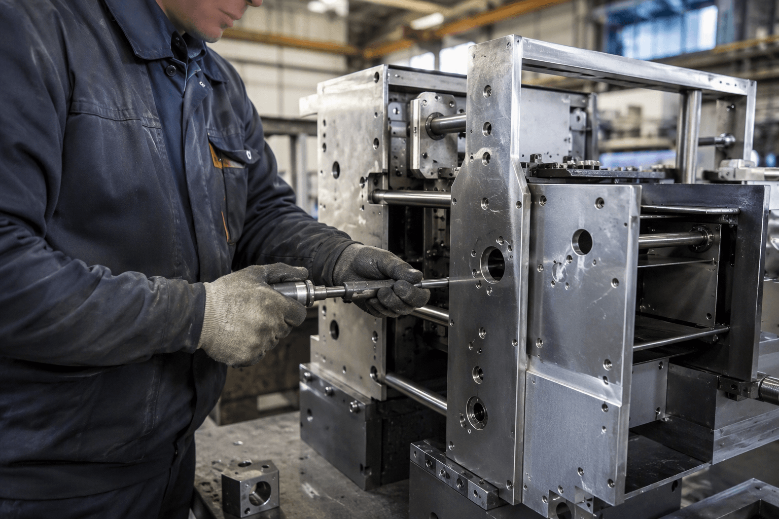
Mechanical parts assembly is the controlled process of fitting and joining individual components into a functional product, module, or subassembly. Depending on the design, it may involve fasteners, locating pins, press fits, retaining features, adhesives, welding, or a combination of methods.
For buyers and engineers, the central question is not simply whether the parts can be connected. The assembly must also match the drawing, maintain the required alignment, allow practical access during production, and support the intended inspection or maintenance plan. Decisions made when designing individual parts can therefore affect assembly time, tooling, consistency, and sourcing.
What Does Mechanical Parts Assembly Include?
The assembly stage begins after the required components have been manufactured or purchased. It covers the actions needed to identify, orient, position, join, adjust, and verify those components. Simple work may consist of installing several screws in a bracket. More involved assemblies may contain sheet metal panels, machined blocks, shafts, bearings, hinges, inserts, seals, and other purchased hardware.
An assembly can be permanent, semi-permanent, or removable. Welded joints and some adhesive bonds are generally intended to remain in place. Bolted joints, clips, and other mechanical fasteners may allow disassembly for repair, replacement, transport, or recycling. Press fits and retaining features fall between these categories because serviceability depends on the specific design and access conditions.
The drawing, bill of materials, and assembly instructions should establish what belongs in the finished unit. When information conflicts or leaves the joining method unclear, that issue should be resolved before production rather than left to operator interpretation.
Assembly Is Not the Same as Part Fabrication
Mechanical parts assembly connects components, but it does not replace the processes used to make them. Keeping these boundaries clear helps buyers identify where a problem originates and what information a supplier needs.
- Sheet metal fabrication creates parts through operations such as cutting, punching, bending, and forming. Those operations establish panel geometry, hole locations, and formed features before assembly.
- Machining removes material to produce features such as bores, faces, pockets, slots, or threads. A machined part may later become one component in an assembly.
- Welding joins materials using heat, pressure, or both, depending on the process. Welding may be one stage of an assembly route, but its heat input and access requirements distinguish it from fastening or fitting operations.
- Finishing applies or modifies a surface for appearance, corrosion control, wear behavior, or another specified purpose. Whether finishing occurs before or after joining depends on the material, finish, joint design, and protected surfaces.
- Assembly brings the prepared parts and hardware together in a defined sequence.
- Inspection checks specified characteristics. It can detect certain discrepancies, but it does not correct an unsuitable design or an uncontrolled process by itself.
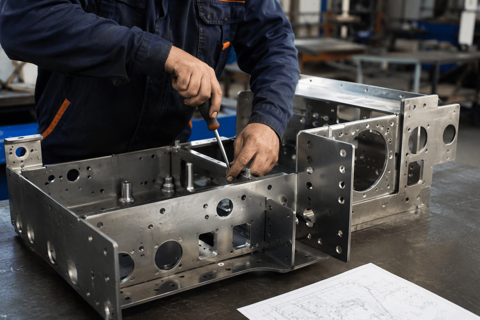
A Typical Mechanical Assembly Workflow
The exact route varies with the product, but a controlled workflow usually follows a recognizable sequence.
- Review the technical package. Confirm the current drawings, revision level, bill of materials, quantities, finish notes, critical dimensions, and any assembly-specific instructions.
- Verify component identity and condition. Parts and hardware are checked against the bill of materials. Obvious damage, contamination, mixed revisions, or missing items should be addressed before work starts.
- Prepare the work area and tooling. Fixtures, hand tools, drivers, gauges, protective materials, and handling equipment are selected according to the assembly.
- Establish the sequence. Components are installed in an order that preserves tool access and avoids trapping a required part behind another feature.
- Locate and join the parts. Datums, tabs, pins, shoulders, fixtures, or mating features establish position while the specified joining method secures the components.
- Perform in-process checks. Orientation, fastener presence, movement, alignment, or another specified characteristic may be checked before later components conceal the joint.
- Complete final verification. The finished assembly is assessed against the applicable drawing and acceptance requirements before packing or transfer to the next operation.
A written sequence becomes increasingly useful when an assembly contains similar-looking parts, concealed fasteners, directional components, or steps that cannot be reversed without damage.
Choosing a Joining Method
No joining method is automatically best. Selection depends on load direction, material, available space, production quantity, service access, appearance, environmental exposure, and whether the product must be taken apart.
Threaded fasteners
Screws, bolts, nuts, and threaded inserts are common where serviceability or straightforward installation matters. The design should provide tool access, suitable thread engagement, and enough surrounding material for the intended joint. If tightening torque or a locking feature is important, it should be stated rather than assumed.
Pins, tabs, clips, and retaining features
These features can locate parts, control orientation, or retain components without relying entirely on threaded hardware. They can also reduce opportunities to install a part in the wrong position. Their suitability still depends on loading, material behavior, forming accuracy, and the required removal method.
Press and interference fits
Press fits depend on the dimensional relationship between mating features. Surface condition, material, geometry, and insertion support can affect the result. Tolerances should be defined from the functional fit rather than assigned independently to each part without considering their combined variation.
Adhesive joining
Adhesives may distribute load or join materials where visible hardware is undesirable. Surface preparation, bond area, curing conditions, and compatibility with coatings or contaminants require consideration. An adhesive specification should not be substituted without review.
Welded joints
Welding can create a permanent structural connection, but joint access, material compatibility, heat distortion, finishing order, and inspection needs must be considered. A welded assembly should not be treated as dimensionally identical to a collection of unwelded parts because heat and restraint can influence final geometry.
The Most Important Technical Decision: How Parts Locate
Fasteners often hold components together, but they do not always locate them precisely. If a design relies on clearance holes alone, parts may shift within the available clearance before tightening. Whether that movement matters depends on the assembly’s function.
Locating pins, machined shoulders, formed tabs, slots, nests, or dedicated fixture surfaces can establish repeatable relationships between components. A useful design separates the locating function from the clamping function where the required alignment justifies it. The chosen locating scheme should also avoid over-constraining the assembly, which can make parts difficult to fit when normal manufacturing variation accumulates.
Datums and critical relationships should be apparent in the technical documentation. Otherwise, one supplier may align external edges while another centers holes or references a fixture surface, producing different interpretations from the same nominal geometry.
Tolerance Stack-Up and Fit
Each manufactured feature has variation. In an assembly, variation from multiple parts can accumulate across bends, hole positions, spacers, coatings, machined faces, and purchased components. This cumulative effect is commonly called tolerance stack-up.
A stack-up review should focus on the dimensions that control function: whether holes align, a shaft enters a bore, a cover closes, a bearing seats, or a moving part retains clearance. Applying tight tolerances to every dimension is not necessarily an effective solution. It may increase manufacturing effort without controlling the relationship that actually matters.
Finish thickness can also affect fit when coated surfaces enter slots, bores, threads, or close-clearance joints. The drawing should indicate any areas that must remain uncoated or be addressed after finishing. When mating components come from different sources, their dimensional assumptions should be reviewed together rather than as isolated parts.
Design and Sourcing Checklist for a Real Project
Before releasing a mechanical parts assembly for quotation or production, use the following questions to identify missing decisions:
- Are the assembly drawing, individual part drawings, and bill of materials on matching revisions?
- Is each purchased component identified clearly enough to avoid substitutions or size ambiguity?
- Which features locate the parts, and which features only clamp or retain them?
- Can tools reach every fastener or joint in the planned sequence?
- Are permanent and removable joints distinguished?
- Are critical fits and functional tolerances identified on the appropriate drawing?
- Does the finish affect threads, grounding points, bearing seats, mating surfaces, or cosmetic alignment?
- Must any characteristic be inspected before another component hides it?
- Is a prototype or first assembly review appropriate before committing to the full quantity?
- Are packing and handling requirements defined for exposed surfaces or movable elements?
For prototype work, the first build can reveal access conflicts, unclear orientation, missing hardware, and sequence problems. Any resulting changes should be incorporated into controlled drawings and instructions so that later production does not depend on informal knowledge.
Request an Application Review Before Your RFQ
If your mechanical parts assembly project includes custom sheet metal components, Yishang can review the available drawing, material, quantity, tolerance, finish, and prototype requirements before quotation. Sharing these details helps clarify manufacturability questions and quotation assumptions without treating incomplete information as final production requirements.
Send the project package through Yishang and identify any critical fits, mating parts, assembly sequence concerns, or supplied hardware that should be considered during the discussion.
Inspection in the Assembly Context
Inspection should be matched to the characteristics that matter to the finished unit. Depending on the design, this may include component identity, overall dimensions, alignment, fastener presence, free movement, visual condition, or another drawing requirement. Not every characteristic can be checked effectively after the assembly is complete.
For example, a concealed joint may require an in-process check before a cover is installed. Final inspection may confirm the completed configuration but be unable to verify an inaccessible internal feature directly. Planning these checkpoints alongside the assembly sequence reduces reliance on assumptions.
Inspection requirements should state what is to be checked and which document defines acceptance. Vague instructions such as “check fit” can lead to inconsistent interpretations unless the required fit or function is described.
Frequently Asked Questions
What hole alignment details should buyers define before requesting a quote?
Buyers should define the functional requirement, drawing notes, critical dimensions, material or process expectations, and any inspection points related to hole alignment. This helps suppliers quote the same manufacturing scope instead of making different assumptions.
How can tolerance stack affect cost, fit, or lead time?
tolerance stack can change tooling, forming, welding, finishing, inspection, or rework requirements. If buyers do not clarify it early, two supplier quotes may look comparable while covering different production risks.
Why should mating parts be reviewed before prototype approval?
mating parts may look acceptable on a single sample but become harder to control during batch production. Buyers should confirm whether the prototype reflects the same process, finish, and inspection conditions expected for production.
What inspection points matter most for mechanical parts assembly projects?
Important inspection points usually include fit-critical dimensions, holes or mating areas, cosmetic surfaces, finish build-up, welded or formed features, and any dimensions that affect downstream assembly. These points should appear in the RFQ or drawing notes.
How can buyers reduce fit-up inspection risk before batch production?
Buyers can reduce risk by clarifying drawings, locking key material and finish assumptions, defining inspection timing, approving a representative sample, and confirming which dimensions or surfaces require tighter process control.
How can Yishang help review mechanical parts assembly requirements?
Yishang can review drawings, RFQ notes, material requirements, tolerance expectations, finish details, samples, and assembly needs to identify unclear assumptions before quoting or batch production.