
For overseas wholesale buyers, sourcing metal products is ultimately a matter of managing risk. Every batch must meet consistent tolerances, assembly must be smooth, surfaces must be clean, and delivery schedules must remain predictable. What many procurement teams do not immediately see is that these outcomes depend heavily on one upstream factor: the types of milling tools a supplier uses.
Cutting tools directly influence dimensional accuracy, surface integrity, cycle time, and long‑run cost stability. When a factory relies on improper milling cutter types, problems become visible in the delivered parts—burrs, uneven edges, chatter marks, tolerance drift, or unpredictable variation from batch to batch. These issues increase inspection time, create assembly delays, and raise the risk of product claims.
For buyers responsible for OEM and ODM programs, this is not a theoretical concern. Tool strategy affects whether a project can move smoothly from sample to pilot run and then to mass production without constant surprises. A supplier’s understanding of milling machine cutter types is therefore part of their process capability, not just a technical detail.
This guide explains how milling tools behave in real metal manufacturing, why tool selection reflects a supplier’s technical maturity, and how buyers can use this knowledge to assess supplier capability—without needing to be machining experts.
How Milling Tools Interact With Metal: Practical Cutting Mechanics
Understanding cutting mechanics helps buyers evaluate whether a supplier truly controls quality at the source. Stable cutting behavior produces stable parts, and unstable cutting quickly shows up as scrap, rework, or hidden assembly cost.
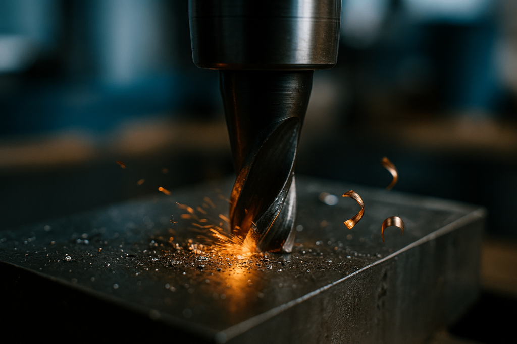
Heat, Chip Load, and Metal Response
Metal cutting is a thermo‑mechanical process. Each material responds differently under load:
- Stainless steel traps heat at the tool’s edge and work‑hardens quickly. Poor chip load or incorrect geometry can accelerate wear, cause dimensional instability, and leave burn marks or surface hardening that complicate later processing.
- Aluminum generates less heat but produces long, sticky chips. If chip evacuation fails, material welds to the tool, damaging finish quality and forcing more frequent tool changes.
- Brass and copper cut cleanly but require proper rake angles to avoid smearing and surface tearing, especially on fine features.
Chip load—the thickness of each chip—is especially important. Too light, and the tool rubs instead of cutting, creating friction and heat. Too heavy, and the spindle overloads or the tool chips. Suppliers who maintain proper chip load typically deliver more consistent results across large batches and reduce the risk of sudden tool failure in the middle of a production run.
Why Tool Geometry Affects Buyer Outcomes
A tool’s geometry—helix angle, flute count, rake angle, and core diameter—determines how it interacts with metal and how the cut behaves over time:
- High‑helix tools clear chips efficiently in aluminum and other non‑ferrous alloys but may lack edge strength in stainless steel.
- Lower flute counts support aggressive roughing and higher material removal rates, but can induce vibration in thin‑wall parts or flexible setups.
- A thicker core improves rigidity for deep pockets or long overhangs, but reduces flute space, limiting chip evacuation in slotting or pocketing operations.
These geometric choices are not just academic. They affect whether parts from the first pallet and the fiftieth pallet still fall inside tolerance, whether edges arrive with manageable burrs, and whether surface quality stays consistent enough to avoid extra polishing or rework. For buyers, stable geometry decisions translate directly into fewer quality incidents and more predictable deliveries.
Types of Milling Cutters and Milling Tools in Metal Manufacturing
Buyers often search for milling machine cutter types, types of mill bits, or types of milling cutters when trying to understand a supplier’s process. Most articles simply list tool names. For real‑world sourcing decisions, it is more useful to view tools in two ways:
- Standard catalog families of milling cutters
- How those tools are applied at different stages of the workflow
This section combines both views so you can quickly connect tool names with their functions in metal manufacturing.
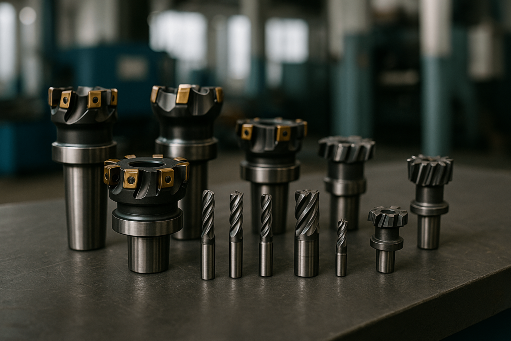
Standard Milling Cutter Families (Catalog View)
In most catalogs and CNC tooling libraries, you will see several standard milling cutter types:
- End mills – Versatile tools that cut with the end and sides, used for slots, pockets, profiles, and general CNC milling.
- Face mills – Larger‑diameter tools used to square stock and machine flat faces quickly with multiple inserts.
- Slab mills and side‑and‑face cutters – Used more on horizontal machines to machine broad surfaces or deep slots.
- Shell mills – Modular cutters where a shell body is mounted on an arbor; common for heavy‑duty face and shoulder milling.
- Fly cutters – Simple single‑point tools for broad, shallow facing when surface finish is more important than speed.
- Form and T‑slot cutters – Special shapes such as T‑slot, Woodruff, and dovetail for undercuts and interlocking features.
The following subsections explain how these and other types of milling tools are actually used in production, grouped by their purpose in the workflow.
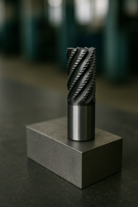
1. Roughing Tools for High Material Removal
Roughing prepares raw stock quickly for precision steps. It is where cycle time can be reduced the most if the right tools and parameters are chosen.
Roughing end mills (serrated hog mills) use a wavy cutting profile to break chips into smaller fragments. This reduces cutting forces, lowers heat, and stabilizes the cut. They are common in heavy steel plate processing, thick brackets, and solid blocks that must be heavily pocketed.
High‑feed cutters run at shallow axial depths but extremely high feed rates. Instead of cutting deep, they rely on high feed per tooth and chip‑thinning effects to remove material efficiently. In high‑volume production, these tools can shorten cycle time significantly, which matters directly to buyers whose cost structure is sensitive to machining hours.
A supplier’s roughing‑tool strategy indicates how they balance productivity, tool life, and thermal control. If they are still doing all heavy cutting with basic end mills, there may be efficiency and stability issues that will show up at volume.
2. Finishing and Semi‑Finishing Tools for Tolerance and Surface Control
After roughing, finishing tools determine whether parts assemble smoothly and meet cosmetic or dimensional standards. This is where small decisions in tooling start to have large effects on buyer satisfaction.
Square end mills cut accurate flat surfaces and pockets, but their sharp corners can chip in hard materials or under unstable conditions. When that happens, tolerance control becomes more difficult and edge quality declines over the course of a batch.
Corner‑radius end mills add a small radius at the edge, improving durability and distributing stress. They maintain repeatable quality in stainless steel or carbon‑steel components and are particularly valuable for metal frames, brackets, and enclosures that require consistent geometry over many production lots.
A reliable supplier always separates roughing from finishing and chooses tools that match the required tolerance and surface quality, rather than relying on a single general‑purpose cutter.
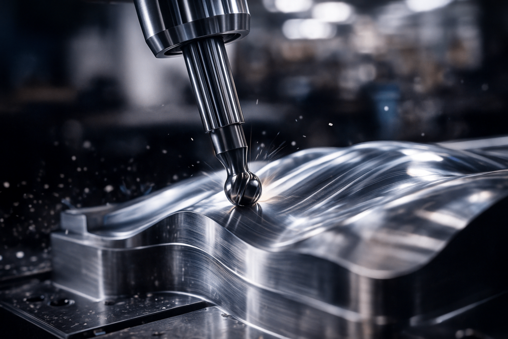
3. Tools for 3D Contours and Aesthetic Surfaces
Many OEM parts require curvature, sculpted surfaces, or decorative geometry. These shapes appear in consumer‑facing metal housings, ergonomic grips, mold inserts, and various display or advertising products.
Ball‑nose end mills provide smooth tool‑to‑surface contact in 3D machining. They are commonly used to produce fillets, organic curves, and free‑form surfaces. The toolpath strategy, step‑over, and step‑down paired with these cutters directly affect surface finish and the amount of hand finishing needed.
Tapered ball mills add rigidity for deep pockets and angled details, reducing deflection while still allowing fine surface control. They are particularly useful when the design demands both depth and precision, such as in structural parts with deep ribs or stylized decorative profiles.
For buyers, the presence of appropriate contouring tools is a sign that the supplier can support more advanced product designs without excessive manual rework or polishing.
4. Tools for Slots, Undercuts, and Assembly Features
Structural and assembled metal products often require functional geometries that cannot be produced with basic tools. This is where more specialized milling cutter types become essential.
Keyseat cutters form precise keyways for mechanical joints and torque‑carrying features. In shafts, couplings, and rotating components, key accuracy directly affects performance and longevity.
T‑slot cutters produce sliding channels used in adjustable systems, metal racks, and modular fixtures. When these features are integral to product adjustment or assembly, dimensional control is critical.
Dovetail cutters generate interlocking profiles for alignment, load support, or slide mechanisms. Proper dovetail geometry can reduce hardware requirements and improve structural integrity.
When sourcing parts with these features, buyers should confirm that suppliers use dedicated cutters rather than trying to approximate shapes with multiple passes from general‑purpose end mills. Dedicated tools normally produce better consistency and lower assembly risk.
5. Tools for Secondary Functional Details
Secondary tools influence assembly quality, safety, and downstream efficiency. They are often the difference between a part that is technically “machined” and one that is truly ready for production use.
Thread mills create cleaner, stronger threads with less risk of breakage than taps, especially in stainless steel or hard alloys. They also provide more flexibility in thread size and depth using a single cutter.
Chamfer mills remove sharpness, protect edges from damage, and improve assembly fit. Consistent chamfering reduces hand‑deburring effort at the buyer’s site and lowers the risk of handling injuries.
Deburring tools address residual edges that appear even after good machining. For high‑volume assemblies, stable deburring practice can significantly reduce line slowdowns and warranty concerns.
Secondary tool usage reflects a supplier’s attention to finishing quality and assembly friendliness—critical for buyers whose own customers judge the final product in their hands.
Summary Table: Common Milling Cutter Types and Their Uses
| Cutter type | Primary role | Typical operations | Buyer relevance |
|---|---|---|---|
| Square / flat end mill | General 2D machining | Slots, pockets, profiles | Core tool for most prismatic metal parts |
| Ball‑nose / tapered ball | 3D contouring and surfaces | Fillets, curves, molds, decorative shapes | Impacts cosmetic quality and hand‑finishing |
| Face mill / shell mill | Large‑area facing | Squaring stock, datum faces | Affects flatness and reference surfaces |
| Roughing end mill / high‑feed | High material removal | Heavy stock removal in plates and blocks | Drives cycle time and machining cost |
| T‑slot / keyseat / dovetail | Functional slots and undercuts | Tracks, keys, interlocking joints | Key to assembly fit and structural behavior |
| Thread mill | Thread creation | Internal and external threads | Reduces thread defects and tap breakage |
| Chamfer and deburring tools | Edge conditioning | Chamfers, deburring, edge breaking | Reduces rework, improves handling and assembly |
This table is not exhaustive, but it covers the milling cutter types most frequently used in CNC metal manufacturing for OEM and ODM projects.
Tool Materials and Coatings: What They Reveal About Supplier Competence
Buyers rarely see the tooling choices behind the scenes, but these choices directly affect the consistency and cost of delivered parts. Understanding basic types of milling tools by material and coating helps you read between the lines when discussing process capability with a supplier.
Carbide vs. HSS: Choosing for the Situation
Carbide tools resist wear and handle heat well, making them well‑suited for stainless steel, tool steel, and other challenging materials. They support higher cutting speeds and often deliver better tool life in rigid setups.
However, carbide can be brittle. In thin walls, unstable fixtures, or deep‑reach situations, carbide tools may chip or fail unexpectedly. Here, HSS tools can offer a more forgiving option with better toughness, at the cost of lower speed capability.
A supplier who adapts tool material to part geometry, metal type, and machine rigidity is more likely to produce reliable batches than one who simply uses the same tools for everything.
Coatings as Process‑Stability Tools
Coatings change how tools handle heat and friction:
- TiAlN / AlTiN support high‑temperature steel cutting by pushing heat into the chip rather than the tool body.
- DLC and polished uncoated flutes reduce adhesion on aluminum and non‑ferrous alloys, lowering the risk of built‑up edge and surface streaks.
These are not purely catalog choices. A factory that aligns coating and surface finish with the specific metal and operation shows a higher level of process understanding. That, in turn, reduces the likelihood of sudden tool‑related quality shifts at volume.
The Compatibility Triangle
High‑level suppliers aim to match:
- Tool material (carbide, HSS, others)
- Tool geometry (flutes, helix, core, profile)
- Tool coating (TiAlN, AlTiN, DLC, uncoated)
- With your metal type and part design
This compatibility triangle is one of the clearest indicators of tooling maturity. It drives predictability and supports long‑term supply stability, which buyers can feel in lower defect rates and clearer cost forecasting.
A Buyer‑Focused Framework for Assessing Tooling Strategy
You do not need to be a process engineer to judge whether a supplier’s tooling strategy is robust. The following framework translates technical behavior into procurement‑relevant signals.
Step 1: Clarify Functional Priorities
Before discussing specifics, align with the supplier on what matters most for each part:
- Dimensional tolerance and fit
- Cosmetic appearance
- Structural strength and fatigue resistance
- Cost efficiency and cycle time
- Assembly speed and ease
Suppliers who ask clarifying questions in these areas are usually building their milling tools selection around your requirements rather than retrofitting your needs to existing habits.
Step 2: Evaluate Tooling Fit for Material and Thickness
Ask how the supplier adapts tooling and parameters when shifting between:
- Sheet metal versus solid blocks
- Stainless steel versus aluminum or galvanized steel
- Thick structural sections versus thin, formed parts
Suppliers who can describe changes in tool choice, chip load, and toolpath when moving between these cases show real process control. Generic answers suggest a more trial‑and‑error approach that may create problems at volume.
Step 3: Confirm Process Segmentation
A mature supplier separates roughing, semi‑finishing, finishing, and secondary operations in both tooling and programming. This segmentation produces more predictable cycle times, tighter tolerance distribution, and fewer unexpected issues during long runs.
If a factory uses one cutter for all stages “to save time,” it often leads to inconsistent quality and unpredictable tool wear—risks that buyers eventually pay for.
Step 4: Review Geometry‑Driven Decisions
Without going too deep into engineering, you can ask how the supplier controls:
- Tool deflection on long overhangs
- Flute count in roughing versus finishing
- Helix angle in different metals
- Run‑out control in tool holding
Their answers will show whether they treat geometry as a lever for process stability or simply rely on standard libraries in their CAM software.
Step 5: Check for Quality‑Impacting Tooling Errors
Ask how they avoid common tooling‑related issues:
- Excessive burrs on thin sheet edges
- Chatter marks in deep pockets
- Thread problems in stainless steel
- Inconsistent chamfers or sharp edges
Suppliers with clear, specific countermeasures generally have fewer surprises and more consistent metrics in day‑to‑day production.
Real Manufacturing Insights That Influence Procurement Results
The following recurring situations connect directly to buyer concerns such as defect rates, rework time, and line stoppage.
Thin Sheet Metal: Vibration and Burr Control
Thin walls and formed sheet parts are inherently flexible. If cutters are too aggressive or geometries are mismatched, vibration and burrs increase. Factories that select higher‑helix tools, optimize step‑over, and control engagement create cleaner edges and more stable dimensions.
For buyers, this means less rework at incoming inspection and faster assembly on their own lines.
Aluminum Components: Chip Adhesion and Surface Finish
Aluminum’s ductility easily produces built‑up edge on tools that lack polished flutes or suitable coatings. The result is streaked surfaces, dimensional drift, or rough textures that must be polished out.
Suppliers with well‑tuned aluminum strategies—appropriate tools, higher spindle speeds, and effective chip evacuation—deliver more uniform finishes and fewer cosmetic issues. This is especially important for visible housings and consumer‑facing components.
Stainless Steel: Heat, Wear, and Tolerance Stability
Stainless steel is unforgiving of poor tooling practice. If chip loads are too low or geometry is unsuitable, tools overheat and wear quickly. This can cause dimensional creep across a batch, even when the first parts passed inspection.
Factories that control chip load, use heat‑resistant coatings, and keep a structured tool‑life management system in place typically provide more stable results in stainless‑steel programs. For long‑term OEM work, this makes a significant difference.
Form Cutters: Cycle‑Time and Consistency Gains
When parts require repeating specialized profiles—dovetail grooves, complex mounting channels, or decorative edge forms—custom profile cutters or form tools often outperform multi‑step machining with standard tools.
From a buyer’s perspective, the presence of form cutters suggests the supplier is willing to invest in efficiency and repeatability for ongoing programs, not just short‑term sampling.
What Overseas Buyers Should Look for in a Supplier’s Milling Capability
You do not need to understand every detail of milling cutter types to evaluate a potential partner. Instead, focus on how transparently the supplier can explain their machining approach and how clearly they link tooling decisions to part requirements.
Consider asking:
- How do you choose among different types of milling tools for my material and geometry?
- What is your strategy to control burrs on thin metal edges?
- How do you prevent chatter in deep pockets or long‑reach conditions?
- Which coatings do you use for stainless versus aluminum, and why?
Pay attention to the specificity and clarity of the answers. Factories that can explain their decisions in straightforward terms usually have stronger internal standards and better machining discipline. That translates into process stability, lead‑time reliability, and long‑term cost efficiency.
FAQ: Common Questions About Milling Cutter Types
Q1. What is the most common type of milling cutter used in CNC machining?
In most metal CNC machining, the most common tools are end mills and face mills. End mills handle slots, pockets, and profiles, while face mills and shell mills efficiently square stock and machine reference faces. Together they cover a large share of day‑to‑day metal milling operations.
Q2. What is the difference between an end mill and a face mill?
End mills cut with both the end and the sides and are used for internal features such as pockets and grooves. Face mills are larger‑diameter tools designed mainly for machining flat surfaces from the top. For buyers, this distinction matters because it affects flatness, surface finish, and cycle time on large flat areas.
Q3. Which milling cutter types are best for aluminum parts?
For aluminum, high‑helix end mills with polished flutes or DLC‑type coatings are preferred, often combined with high‑speed spindle settings and strong chip evacuation. Face mills with sharp, positive‑rake inserts are also common for squaring plates and extrusions. These choices reduce built‑up edge and help maintain consistent surface appearance.
Q4. How should suppliers choose milling tools for stainless steel?
In stainless steel, suppliers usually favor solid carbide tools or coated insert cutters with robust geometry and coatings such as TiAlN or AlTiN. Maintaining adequate chip load and using stable toolholders help control heat and wear. Buyers can ask about these factors to gauge whether the supplier’s strategy will stay stable at volume.
Q5. Do more flutes always mean a better milling cutter?
Not necessarily. More flutes can increase feed rate potential but reduce chip space. In roughing or when slotting in softer metals, too many flutes can clog the flutes and raise heat. The right flute count depends on material, engagement, and whether the tool is used for roughing or finishing.
If you need guidance on tooling strategies for your project or want to discuss how milling decisions affect quality and cost, the YISHANG engineering team can support your evaluation and provide practical manufacturing insight tailored to your metal products.
