The Real-World Cost of Getting It Wrong
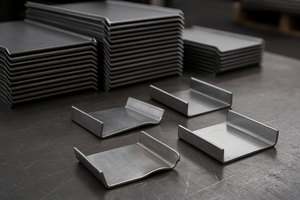
A U.S.-based importer placed a bulk order for custom aluminum enclosures. Their engineering team set a 0.060″ bend radius—the default in their CAD system. On the shop floor, cracks emerged during forming. Rework became necessary, causing thousands in material waste and significant shipping delays.
This wasn’t just a design misstep—it exposed a disconnect between digital models and actual fabrication processes. For global wholesale buyers, these mismatches often lead to rework, misalignment, and cascading lead time delays.
At YISHANG, we’ve found that defining the correct bend radius early—based on material, thickness, and tooling—prevents over 80% of production inconsistencies. Smart sourcing starts with precise specifications—especially in custom enclosure manufacturing projects. For high-volume OEM production, a defined bend radius isn’t just preferred—it’s a baseline for quality control. Define your spec, control your cost.

Why CAD Defaults Can Mislead
Most CAD platforms apply a default bend radius—often around 0.100″—which doesn’t reflect real shop floor setups.
In real-world fabrication, bend tools are usually aligned to material thickness—typically 1×T. If your CAD drawing calls for a radius not supported by standard tooling, it can delay production or require expensive adjustments.
Moreover, design software rarely accounts for:
Springback variation
Material grain orientation
Coating or surface finish stress
Even a perfect digital file can produce flawed physical parts if the bend specs ignore these real-world variables.
Pro tip: Align your RFQ bend radius with supplier tooling capabilities, especially when requesting tight-tolerance sheet metal components. It’s a quick step that avoids long delays.
Good parts start with great drawings.

How to Select the Right Bend Radius
Some assume any mailbox works with couriers. Only engraved steel boxes with barcode plates meet DHL/UPS intake standards.
Material Thickness
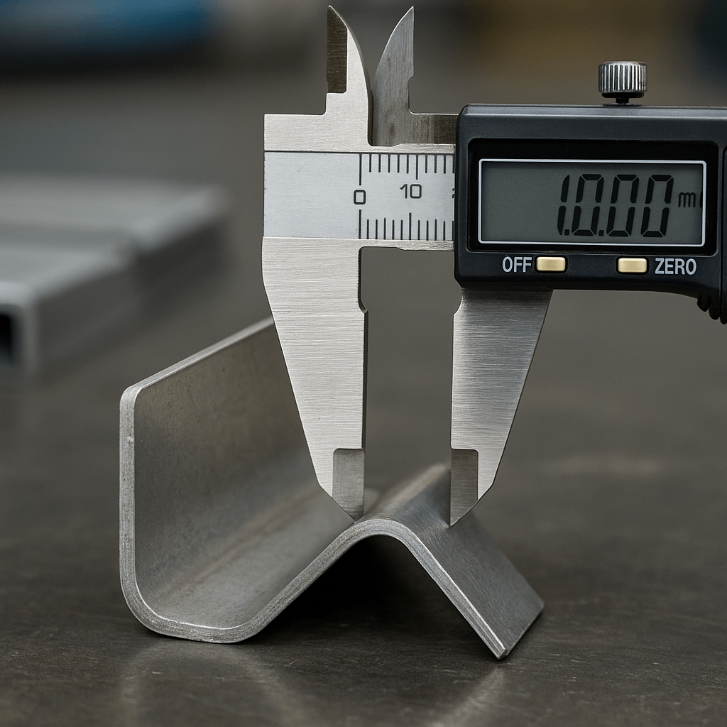
Thicker materials resist bending. For example, 3mm stainless steel requires a noticeably larger radius than 1mm mild steel to avoid cracking.
Material Type
Aluminum (6061-T6): Prone to cracking; use larger radii or softer alloys
Stainless Steel: Lower ductility; 1.5×T is a safer minimum
Copper / Brass: More flexible; suitable for tighter bends
Forming Process
Air Bending: Versatile and common
Bottoming: Precise but tool-limited
Coining: Most accurate, suitable for mass production with consistent specs
Table: Minimum Recommended Bend Radii
| Material | Min. Radius (× Thickness) | Notes |
|---|---|---|
| Mild Steel | 1.0×T | Common and cost-effective |
| Stainless Steel | 1.5×T | Helps prevent internal cracking |
| Aluminum 5052 | 1.0–2.0×T | Use softer alloys for sharper bends |
| Brass / Copper | 0.5–1.0×T | Ideal for cosmetic and decorative use |
Also consider K-Factor, springback, and bend allowance/flat pattern length—especially important in thin-gauge or high-repeatability jobs.

When the Standard Radius Isn’t Enough
While a 0.030″ bend radius is a helpful default, it doesn’t suit every material or geometry.
With Thicker Materials
Using a 0.030″ radius on 0.1875″ stainless steel is likely to cause fractures. Best practices:
≥ 0.060″ for 0.125″ thickness
≥ 0.090″ for 0.1875″ thickness
Correct radii improve product durability and reduce tool wear.
With Coated or Brittle Metals
Anodized aluminum or powder-coated steels may crack or flake. Slightly increasing the bend radius helps preserve finish and functionality.
With Tight Assembly Tolerances
When components are meant to interlock or be stacked, even small deviations in flange geometry affect fit. In such sheet metal OEM sourcing scenarios, precise bend control becomes mission-critical.
Undefined Radius = Risky Manufacturing
Failing to specify a bend radius in your technical drawings transfers key decisions to the fabricator.
The consequences include:
Inconsistencies across batches
Unanticipated flange or hole misalignment
Cosmetic variations across identical SKUs
Tip for purchasing teams: Always define tolerances and expectations upfront—especially for repeat or wholesale tolerance targets.
How Correct Bend Radius Lowers Cost
Bend radius doesn’t just impact shape—it directly affects cost-efficiency in large-scale runs.
When your radius matches standard shop tooling:
There’s no need for custom dies
Tooling changeover times drop
Consistency improves over long batches
One YISHANG client reduced their per-unit cost by 12% simply by adjusting their drawings to match our press brake library. This also eliminated a 3% scrap rate due to cracked flanges.
Defined specs allow better cycle times, lower reject rates, and consistent quality in global OEM sourcing. This is especially important in repeat orders where dimensional drift compounds over time.
Validate Your Specs Before Production
Before locking in volume production, confirm your bend radius with simulation or real-world validation.
Run FEA Simulations
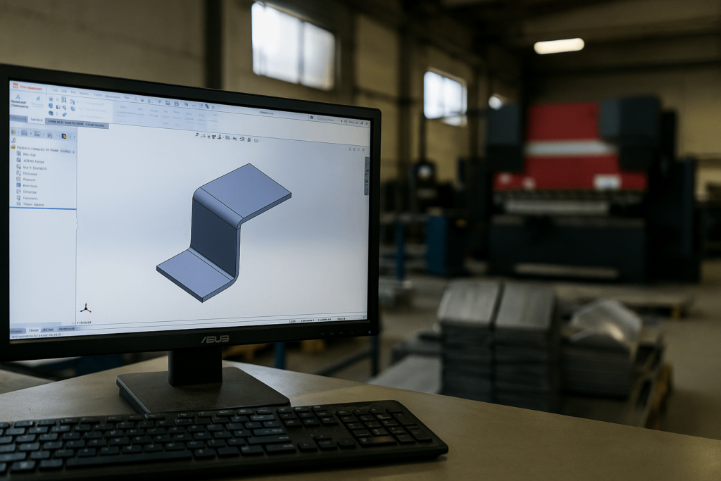
Software like SolidWorks or AutoForm helps visualize bend behavior. Identify cracking or springback risks early.
Use Industry Tools
Free calculators on sites like SheetMetal.Me let you validate bend allowances based on material and thickness. Some suppliers embed these tools in their RFQ process to help buyers finalize drawings efficiently.
Test a Small Batch
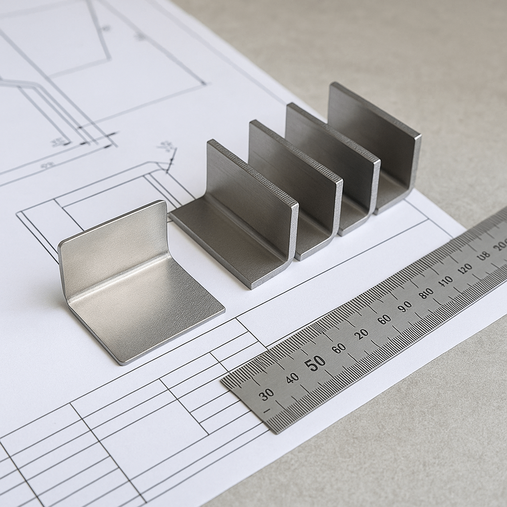
Order a 3–5 piece sample to confirm forming accuracy—ideal for low‑volume sheet metal fabrication pilots. It’s low‑risk and saves thousands later.

Buyer-Focused Bend Radius FAQs
Q1: Why not use the CAD default 0.100″ bend radius?
Because it’s not based on real tooling. Defaults can create conflicts in fabrication, leading to costly rework.
Q2: Should I match inside radius to material thickness?
It depends. It’s often fine for mild steel, but brittle alloys like 6061-T6 may require larger radii.
Q3: Will bend radius affect flange length?
Yes. Tight radii shorten flanges. Be sure to calculate deductions accurately. Poor flange specs can delay shipment in sheet metal OEM sourcing workflows.
Q4: Can I include a radius range in my quote request?
Yes—and it’s encouraged. For example, 0.030″–0.050″ lets suppliers pick tooling that’s efficient and in stock.
Q5: Does YISHANG review bend radius specs in RFQs?
We do. We’ll check your drawings and optimize them for fabrication and consistency.
Q6: What’s ideal for aluminum parts in volume?
6061-T6: minimum 1.5×T. 5052: 1×T works well.
Q7: What’s considered “standard” bend tooling in fabrication?
Most shops use radii around 1×T or 1.5×T. Always confirm before production.
Q8: Can I change the bend radius mid‑order without retooling?
Usually not without trade‑offs. Changing radii mid‑run can affect tooling selection, flat pattern development, flange lengths, and delivery dates. Align on a radius range during RFQ to avoid rework.
Final Takeaway: Accuracy Drives Efficiency
In bulk sheet metal procurement and export‑grade quality control, tolerances like bend radius are not small details—they define your end result.
Buyers engaged in precision OEM sheet metal sourcing who set realistic, supplier-aligned specs benefit from:
Lower part rejection rates
Shorter delivery timelines
Reduced per-unit cost across repeat orders
At YISHANG, we help procurement teams streamline fabrication by validating specs early. Backed by ISO 9001 and RoHS‑compliant processes, we focus on repeatable quality without added hype.

