
Introduction: The Ticking Clock of Tool Wear and Its Impact on Your Bottom Line
In the relentless pursuit of efficiency and profitability, modern manufacturing faces a persistent challenge: the machining of advanced materials. High-silicon aluminum alloys, carbon fiber reinforced polymers (CFRP), and abrasive composites—especially prevalent in the automotive, aerospace, and electronics industries—pose serious machining difficulties.
For any business operating on tight production margins, relying on conventional carbide tools for such materials represents an operational risk. Each rotation gradually erodes the cutting edge, increases heat, and contributes to dimensional inconsistencies. This accelerated tool wear sets off a ripple effect: more frequent tool changes, unexpected downtime, inconsistent part quality, and ultimately, a higher total cost per part.
In this demanding production landscape, incremental improvements are no longer sufficient. Production engineers, CNC supervisors, and sourcing managers require transformative solutions that redefine machining economics. This is where Polycrystalline Diamond (PCD) inserts shift from being a premium option to a strategic necessity.
PCD tooling leverages the unmatched hardness of synthetic diamond to overcome abrasive wear. The result? Exponential gains in tool life, surface finish, and dimensional stability—especially for high-volume, non-ferrous CNC applications. This article is a decision-making playbook, presenting a data-driven and application-specific case for PCD inserts. We go beyond surface-level marketing and dive into material science, machining dynamics, application matching, cost modeling, and workflow integration.
What is a PCD Insert, Really? Deconstructing a High-Value Production Asset
From Diamond Dust to Dominance: The Science of HPHT Sintering
The creation of PCD is a testament to modern material science, replicating the geological conditions found deep within the Earth. The process, known as High-Pressure High-Temperature (HPHT) sintering, begins with micron-sized synthetic diamond particles. This diamond powder is placed against a tungsten carbide substrate within the reaction chamber of a massive industrial press.
The assembly is subjected to immense pressures (5–8 GPa) and extreme temperatures (1400–1800°C). Under these conditions, a cobalt binder from the carbide substrate liquefies and infiltrates the diamond powder. This acts as a solvent-catalyst to fuse the individual diamond grains into a cohesive, interlocking polycrystalline layer permanently bonded to the substrate. This meticulous process transforms simple carbon into a high-value production asset capable of withstanding incredible wear.
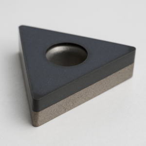
The Anatomy of an Edge: A Composite Engineered for Performance
A PCD insert is a “composite of composites,” a layered system where each part is engineered for a specific function. The cutting layer consists of a dense concentration of diamond grains (90–95% by volume) held in a cobalt binder matrix. The cobalt is essential, providing the toughness needed to support the brittle diamond structure. However, it also defines the tool’s primary limitation: at temperatures above 750°C, cobalt can catalyze the degradation of diamond, especially when machining iron-based materials.
The tungsten carbide substrate acts as the resilient backbone, providing mechanical support and impact resistance to withstand the immense forces of high-speed machining. It also offers a reliable surface for brazing the PCD tip onto a tool body, ensuring a robust and durable final product. This intelligent material combination delivers the best of both worlds: the extreme hardness of diamond at the cutting edge and the toughness of carbide for structural integrity.
The Grain Size Spectrum: Tailoring Performance to Your Application
Sourcing the correct PCD tool requires matching the grade to the application. PCD is a family of grades, each defined by its diamond grain size, which dictates the trade-off between wear resistance and edge quality.
- Fine Grain (2–5 µm): Offers the highest toughness and can be honed to the sharpest edge. Ideal for mirror-like surface finishes (Ra < 0.4 µm) and machining composites that demand a clean shear to prevent delamination.
- Medium Grain (10 µm): A versatile workhorse that balances abrasion resistance with toughness—reliable for machining low-to-medium silicon aluminum and many woodworking composites.
- Coarse Grain (25 µm+): Delivers exceptional abrasion resistance and thermal stability. This grade is engineered for aggressive applications like high-silicon aluminum (>13% Si), MMCs, and green ceramics.
- Multimodal/Mixed Grain (2–30 µm): Combines various grain sizes to deliver both wear resistance and superior edge strength. Excels in machining highly abrasive and bimetal applications.
The PCD Advantage: A Direct Impact on Your Bottom Line
For procurement leaders and production managers, the value of a cutting tool lies in its capacity to reduce costs, increase throughput, and ensure quality. PCD tooling delivers on all three fronts, offering tangible benefits that directly influence profitability.
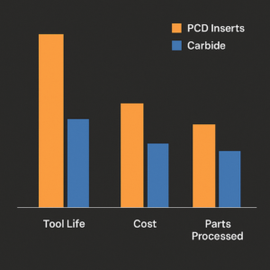
The Hard Data: Head-to-Head Cutting Tool Comparison
A data-driven comparison reveals why PCD is the superior choice for its intended applications. Its properties are not merely incrementally better—they belong to an entirely different performance class.
| Feature | Polycrystalline Diamond (PCD) | Cubic Boron Nitride (CBN) | Tungsten Carbide (Coated) | Ceramic (Al₂O₃/Si₃N₄) |
|---|---|---|---|---|
| Hardness (HV) | >10,000 (diamond) | ~4,500 | ~1,200 – 2,400 | ~1,800 – 2,200 |
| Toughness | Low | Low-Medium | High | Very Low |
| Max Temp (°C) | ~800 (reacts with Fe >700°C) | >1,000 | ~900 | ~1,200 |
| Thermal Conductivity | Very High (700 W/mK) | High | Medium | Low |
| Primary Applications | Non-ferrous metals (Al, Cu), Composites, Wood, Plastics | Hardened Steels (>45 HRC), Cast Irons, Superalloys | Steels, Stainless Steels, General Purpose Machining | High-speed finishing of Superalloys, Cast Irons |
7 Quantifiable Benefits That Drive Business Value
- Unprecedented Tool Life & Durability: A single PCD edge can last 50–100x longer than carbide in high-volume abrasive production—cutting annual tooling spend dramatically.
- Higher Throughput via Increased Speeds: With cutting speeds reaching up to 6,000 m/min in aluminum milling, PCD significantly reduces cycle times.
- Superior Quality & Reduced Rework: Low friction and stable edge retention minimize built-up edge, often eliminating the need for secondary finishing.
- Guaranteed Part-to-Part Consistency: Precision is maintained over thousands of parts, ensuring dimensional stability and reducing scrap.
- Maximized Machine Uptime: Fewer tool changes mean more production and less idle time.
- Lower Total Cost-Per-Part: Despite higher upfront costs, overall expenses drop when factoring in tool longevity and efficiency.
- Enhanced Sustainability: Reconditionable tools support circular economy models and reduce environmental impact.
The PCD Application Matrix: Where Performance Meets Profitability
PCD tooling isn’t a one-size-fits-all solution—it thrives where conventional tooling fails. Understanding its performance envelope allows manufacturers to unlock its full ROI potential across specific industry verticals.
Automotive: Precision at High Volumes
High-silicon aluminum components like engine blocks, pistons, and transmission housings challenge conventional tooling due to their abrasive nature. PCD not only survives, but thrives in these conditions, delivering micron-level accuracy at high feed rates—critical for just-in-time (JIT) automotive workflows.
Aerospace: Machining Composites without Compromise
Carbon fiber, aramid fiber (Kevlar), and honeycomb sandwich structures demand clean shearing to prevent delamination or fiber pull-out. PCD tools—especially fine-grain and laser-cut variants—provide unmatched edge retention and surface integrity for CFRP skin panels, rib structures, and interior composites.
Electronics & Semiconductors: Micro-Machining with Zero Burrs
Copper, graphite, and ceramic substrates for IC packaging and chip carriers require ultra-fine features with burr-free surfaces. PCD inserts achieve micro-finishing tolerances that eliminate post-machining cleaning and hand-polishing.
Energy & Storage: Handling Composite and Abrasive Layers
In battery module and green energy hardware production, layered composites and thermally conductive materials (like graphite-filled polymers) present tool-wearing nightmares. PCD inserts ensure low thermal load and consistent depth of cut for high-yield fabrication.
Furniture, Wood & Plastic: Production at Industrial Scale
PCD is a staple in high-speed panel processing for MDF, HDF, melamine, and laminated boards. Multimodal PCD grades extend edge life even on glue-line contaminated sections, reducing tool swaps and enabling higher OEE (Overall Equipment Effectiveness).
Engineering the Perfect Cut: Factors That Influence PCD Tool Selection
Choosing the right PCD insert is not a one-size-fits-all decision. Each machining operation has its own thermal loads, surface finish expectations, tool path dynamics, and substrate interaction. A strategic selection process, guided by application-specific criteria, ensures maximum return on tooling investment.
1. Workpiece Material Composition
High-silicon aluminum alloys (>13% Si) demand coarse-grain PCD grades for their abrasive nature, while CFRPs and fiber-reinforced plastics benefit from ultra-sharp fine-grain PCD to prevent delamination. Matching insert grade to substrate hardness and abrasiveness is fundamental.
2. Cutting Conditions: Speed, Feed, and Depth of Cut
Higher cutting speeds require thermally stable tool grades, while aggressive depths of cut favor inserts with reinforced edge geometries. For low-force, high-rpm machining in thin-walled structures, sharp-edged tools with fine grains reduce risk of deflection and chatter.
3. Machine Tool Rigidity & Tool Holder Type
A high-performance insert cannot compensate for machine instability. Applications with limited rigidity (e.g., multitasking machines or long-reach setups) benefit from chamfered or honed PCD geometries that dampen vibrations.
4. Edge Preparation & Chip Control
Laser-cut or ground-edge inserts offer different chip evacuation behaviors. Inserts for ductile non-ferrous metals may feature negative rake or chipbreaker geometries, while brittle composites require honed or razor-sharp edges to avoid fiber pull-out.
5. Surface Finish & Dimensional Tolerance Targets
When mirror-like finishes are mission-critical—such as in reflector housings or sealing surfaces—choose fine-grain PCD with minimal edge wear propagation. In contrast, when tolerances trump aesthetics, medium-to-coarse grain PCD often delivers more stable performance over time.
Failure Modes & Diagnostics: When Even Diamonds Struggle
Despite PCD’s exceptional hardness, it is not immune to failure. Understanding common wear mechanisms helps extend tool life and improve machining reliability.
1. Edge Chipping
Often triggered by interrupted cuts, poor fixturing, or excessive feed rates, edge chipping occurs when the mechanical shock exceeds the tool’s fracture threshold. Rounded or chamfered edges mitigate this risk.
2. Abrasive Wear
This occurs gradually as hard particles within the workpiece erode the diamond grains. Coarse grain PCD resists abrasive wear better due to its larger diamond crystals and stronger grain boundary structure.
3. Thermal Degradation
At elevated temperatures, the cobalt binder may catalyze diamond graphitization, especially in ferrous metal applications. Maintaining optimal cutting parameters and using minimal lubrication (in dry machining) prevents excessive thermal loads.
4. Delamination or Cratering
In layered composites or fiber materials, poor edge design can lead to subsurface tearing or micro-cratering. Switching to sharper edge geometry and adjusting rake angle can reduce such failures.
5. Flank & Crater Wear
Seen as gradual breakdown on the clearance or rake face, typically due to excessive heat, high cutting speeds, or insufficient edge preparation. Monitoring tool wear visually or through in-line sensors is vital.
ROI and Cost Modeling: Is PCD Worth the Investment?
For procurement and financial stakeholders, the question is not simply whether PCD performs well—but whether it performs profitably. This means evaluating PCD investment through total cost modeling and not just price-per-insert.
1. Tool Life Multiplier Effect
A PCD insert lasting 60 times longer than carbide eliminates 59 tool changes. Each change avoided saves operator labor, machine setup time, and reduces production interruptions—accumulating thousands of dollars in hidden savings.
2. Reduced Scrap and Rework Costs
Stable edge retention ensures tighter tolerances and repeatable finishes across high part volumes. Fewer out-of-tolerance parts mean less rework, less inspection burden, and reduced material waste.
3. Cycle Time Reduction
Faster feeds and speeds enable greater part output per shift, improving machine utilization. For high-volume OEMs, even a 10% cycle time gain translates into significant annual revenue increase.
4. Lower Tool Inventory and Handling Overhead
Longer-life tools reduce the frequency of procurement, inventory turnover, and tool crib management—streamlining internal logistics.
5. Reconditioning and Resharpening Potential
Unlike single-use inserts, many PCD tools can be reconditioned 2–3 times, reducing lifetime cost-per-cut further and supporting sustainability initiatives.
6. Total Cost per Part (TCP) Model
Factoring in purchase price, tool life, changeover time, labor, scrap, and regrind cost, PCD inserts often outperform carbide with 30–60% lower TCP in the right application environment.
Final Thoughts: Integrating PCD Into Your Workflow
PCD tooling is not just a technical upgrade—it’s a strategic lever that enhances operational excellence, cost-efficiency, and competitive edge. When thoughtfully implemented into a machining environment, it contributes directly to lean production targets, sustainable operations, and consistent part quality over high-volume runs.
The best path to PCD integration is a phased validation process. Start with components where surface quality, tooling life, or cutting consistency is already impacting ROI—especially in abrasive non-ferrous applications. Benchmark performance through limited production trials, using testable KPIs such as edge degradation rates, cost per part, and cycle time efficiency.
Once validated, scaling PCD use to similar operations brings exponential gains. This structured rollout approach helps maximize the return on investment while reducing risk and disruption to existing processes.
YISHANG, with 26+ years of OEM and ODM experience in global metal parts manufacturing, assists procurement and engineering teams in applying advanced tooling like PCD inserts into actual production lines. Our engineers help optimize tooling geometry, material selection, and cutting parameters to align with specific workpiece profiles and production goals.
Whether you’re machining high-silicon aluminum, CFRP composites, or layered thermal materials, the strategic use of PCD inserts can eliminate repeat failures, enhance throughput, and improve your bottom line. In competitive global manufacturing, the right tooling partner—and the right insert—can make all the difference.
