
Introduction: Beyond RPM – The Language of Manufacturing Reliability
In manufacturing, success is measured in precision, efficiency, and reliability. For procurement managers vetting a supplier, the core question is one of trust: does this company possess the deep process control needed to deliver consistent, high-quality parts on schedule and on budget? The answer lies not in the machinery alone, but in a mastery of the fundamental physics of metal cutting.
While many focus on Revolutions Per Minute (RPM), the true metric of expertise is SFM (Surface Feet per Minute). SFM, or surface speed, is the actual velocity at which a tool’s cutting edge engages a material’s surface. This single variable governs heat, tool life, and final part quality. This playbook is designed to demonstrate the core principles that define a reliable manufacturing partner. At YISHANG, we believe that mastering SFM is the key to the quality assurance and production efficiency our clients demand.
Pro Tip: Use an online machining SFM calculator to compare values between tool diameters and materials. This is a great entry point for evaluating a supplier’s process know-how.
Cracking the Code: Why SFM Matters More Than RPM in Procurement
The foundational shift from an amateur to a professional machining mindset is moving from an RPM-first to an SFM-first approach. SFM represents the scientific goal—the optimal linear speed a specific material requires to be cut cleanly. RPM is merely the machine’s action to achieve that goal for a given tool diameter.
To grasp this, consider the record player analogy. A point near the center of a record and a point at the outer edge both complete 45 revolutions per minute, but the outer point travels a much greater linear distance. SFM is that linear distance. This is why a tiny end mill must spin incredibly fast to achieve the same effective cutting speed as a large face mill.
For a procurement manager, this distinction is critical. A supplier who only thinks in RPM is guessing. A supplier like YISHANG, who masters SFM, is controlling the process scientifically. This control directly impacts machining economics. The correct SFM reduces tool wear, shortens cycle times, and ensures part quality. It is the primary lever for controlling the cost-per-part and the reliability of an entire production run.
The Physics at the Cutting Edge: How SFM Dictates Success or Failure
Understanding SFM is to understand the intense, microscopic battle at the tool’s tip. Machining is a process of controlled material failure through shearing, and nearly all the energy involved is converted into heat. A supplier’s ability to manage this thermal energy is a direct indicator of their expertise and a cornerstone of quality control.
The Science of Heat and Its Impact on Quality
Heat in machining originates in two locations: the primary shear zone, where the material deforms into a chip, and the secondary shear zone, the interface where the chip slides across the tool. Higher SFM increases the rate of shearing and friction, directly increasing heat generation.
The goal of modern high-speed machining is not to eliminate this heat, but to strategically manage its destination. In an optimized cut, up to 90% of the heat is contained within the chip and rapidly evacuated. This is a critical process control that keeps the tool and workpiece thermally stable, ensuring dimensional accuracy and preventing metallurgical damage to the part.
The SFM “Sweet Spot”: A High-Stakes Balancing Act
Every tool and material combination has an optimal SFM range—a “sweet spot” that balances productivity with process stability. Deviating from this range is a hallmark of an uncontrolled process and leads to predictable, costly failures.
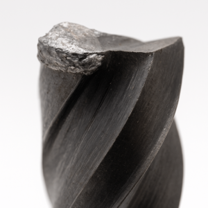
The Danger of “Too Fast”: When SFM is excessive, heat is generated faster than it can be evacuated. This thermal overload soaks into the cutting tool, triggering destructive wear mechanisms like plastic deformation, accelerated flank wear, and crater wear. For the client, this translates directly into higher tooling costs, increased machine downtime for tool changes, and the risk of production delays.
The Danger of “Too Slow” and Built-Up Edge (BUE): Counterintuitively, running too slowly is just as damaging. Insufficient surface speed causes the tool to “rub” or “plow” instead of cleanly shearing the material. This generates intense frictional heat and creates the perfect conditions for a Built-Up Edge (BUE).
The Finish Line: The Built-Up Edge (BUE) Phenomenon
A Built-Up Edge (BUE) is an accumulation of workpiece material that pressure-welds itself to the tool’s cutting edge. It is most common at low cutting speeds in ductile, work-hardening materials like certain steel and aluminum alloys.
The BUE grows until it becomes unstable and fractures. A portion embeds itself into the freshly machined surface, creating a rough, torn, and unacceptable finish that will fail quality inspection. This destructive cycle also tears away microscopic pieces of the tool, causing unpredictable and premature failure. A supplier that cannot control BUE cannot guarantee surface finish or dimensional consistency, making them a significant liability.
The Machinist’s Toolkit: From Calculation to Application
A professional supplier moves beyond theory and implements a systematic approach to process control. This begins with calculation but is refined by deep, hands-on experience.
The Formula for SFM (And Why It’s Just the Start)
The mathematical bridge between the scientific goal (SFM) and the machine setting (RPM) is a straightforward formula:
Calculating RPM from SFM (Imperial):
RPM = (SFM × 3.82) / Diameter(inches)
This formula is fundamental, but treating it as the final word is a common mistake. It provides a starting point, but true process control comes from understanding the variables that demand intelligent adjustment to achieve the desired surface speed.
Decoding Manufacturer Charts (And Their Hidden Limitations)
Tooling manufacturers provide speed and feed charts that serve as a baseline. However, an experienced manufacturing partner like YISHANG knows that these charts are developed under ideal laboratory conditions and are often conservative.
Relying on them blindly without adjustment is a sign of inexperience. True expertise is demonstrated by the ability to interpret these values and intelligently modify them based on the real-world conditions of a specific production run, ensuring optimal performance and tool life.
The Hierarchy of Influence
The optimal SFM is the result of a complex system of interacting variables. Our process control involves evaluating this entire hierarchy for every project:
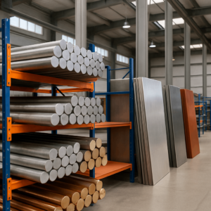
- Workpiece Material
- Cutting Tool Material & Coating
- Machine Rigidity & Tool Overhang
- Coolant Application
Actionable SFM Starting Points (Quick Reference Table)
| Material | Recommended SFM Range | Tool Material | Notes for Procurement |
|---|---|---|---|
| Aluminum (6061, 7075) | 800–1500+ | Carbide / Coated Carbide | High SFM tolerable; verify if chip evacuation is optimal |
| Mild Steel (1018) | 100–250 | HSS / Carbide | Watch for BUE at low speeds; coolant use is key |
| Stainless Steel (304, 316) | 70–150 | Coated Carbide | Thermal management critical; avoid aggressive ramping |
| Inconel / Hastelloy | 20–50 | High-Grade Coated Carbide | Requires rigid setup and optimized toolpath strategies |
| Brass / Copper | 300–800 | Carbide | Good thermal conductivity; adjust feed to avoid burring |
| Titanium Alloys | 60–120 | Coated Carbide | Poor thermal conductivity; strong heat concentration |
SFM in the Real World: Process-Specific Battle Plans
Turning (Lathe Work)
Turning operations generally involve constant engagement between the tool and the rotating workpiece. Here, SFM directly controls heat generation, chip evacuation, and surface finish. G-code commands like G96 (constant surface speed) allow the lathe to adjust RPM in real-time to maintain a consistent SFM as the cutting diameter changes.
Milling (End Milling, Face Milling)
In milling, the cutter rotates, and the workpiece feeds into it. Because the cutter has a fixed diameter, the only way to control SFM is through RPM. Since tools vary widely—from tiny micro-end mills to large face mills—selecting the correct RPM to match the material and desired SFM is critical.
Drilling
Drilling combines aspects of turning and milling but adds unique challenges. The cutting edges are poorly cooled, chips are difficult to evacuate, and center speeds are effectively zero. The SFM must be carefully balanced to prevent tool breakage.
Level Up: From Operator to Artisan – Reading the Cut in Real-Time
Mastery of SFM doesn’t stop at the calculation or machine setting. The final layer of expertise lies in real-time observation. Seasoned machinists use their senses—sound, sight, touch—to read the cut and make micro-adjustments.
Auditory Cues
A crisp, steady tone often indicates a healthy cut within optimal SFM. Screeching, whining, or inconsistent rhythms suggest problems: chatter, tool wear, or incorrect speed/feed combinations.
Visual Inspection: Chips Don’t Lie
Chip shape, color, and behavior are critical indicators:
- Color: Straw or blue chips in steels can indicate excessive heat.
- Shape: Short, curled chips suggest clean shearing.
- Flow: Continuous, smooth chip evacuation reflects good surface speed.
Surface Finish and Part Temperature
A mirror finish or consistent texture confirms optimal SFM. If a part emerges hot to the touch despite coolant use, it suggests improper chip evacuation or overly aggressive parameters.
Tool Wear Patterns
By monitoring wear marks—especially flank and crater wear—our technicians backtrack to likely causes such as excessive SFM, lack of coolant, or improper toolholder setup.
Conclusion: SFM is Not a Setting, It’s a Strategy for Reliability
Surface Feet per Minute (SFM) is more than a formula—it is a core principle that separates high-precision manufacturers from the rest. For procurement teams evaluating suppliers, the ability to control and optimize SFM is a proxy for broader operational excellence.
At YISHANG, SFM is not treated as a fixed number on a spec sheet. It is a dynamic parameter—constantly evaluated, tuned, and refined based on tool wear, material behavior, machine condition, and production targets.
When a supplier talks in SFM, they are speaking the language of thermal control, dimensional accuracy, tool longevity, and cost efficiency. It is the vocabulary of process reliability.
For every project, our goal is not just to machine a part—it’s to deliver confidence in every cut. That confidence begins with mastering SFM.
FAQs (Frequently Asked Questions)
📐 Technical Terms & Definitions
Q1: What’s the difference between RPM and SFM in machining?
A: RPM (Revolutions Per Minute) is the rotational speed of the tool. SFM (Surface Feet per Minute) is the linear speed at which the tool engages the material. SFM varies with tool diameter and is the critical factor in controlling heat and tool life.
Q2: How do I calculate SFM manually in machining?
A: Use the formula: RPM = (SFM × 3.82) / Tool Diameter (in inches). You can also use free online SFM calculators to speed up evaluation and prevent manual errors.
Q3: What’s the difference between SFM and cutting speed?
A: SFM is a unit that expresses cutting speed in surface feet per minute. Cutting speed is a broader term, while SFM is the specific measurement used in imperial units for CNC operations.
Q4: Is there a recommended surface speed chart or calculator I can use?
A: Yes. Most tooling manufacturers provide surface speed charts, and there are SFM calculators online. These tools help you evaluate whether your supplier’s cutting parameters fall within professional ranges.
🛠 Procurement & Application
Q5: How do I know if my supplier is using proper SFM settings?
A: Ask if they use G96 (constant surface speed) in lathe operations, monitor chip formation and tool wear, and adjust feeds/speeds based on material and tool conditions. A competent supplier will explain their rationale for chosen SFM values.
Q6: Can higher SFM always improve productivity?
A: Yes. Most tooling manufacturers provide surface speed charts, and there are SFM calculators online. These tools help you evaluate whether your supplier’s cutting parameters fall within professional ranges.
Ready to evaluate your machining strategy?
Let YISHANG help you fine-tune your project’s surface speed strategy for consistent output, reduced tooling costs, and superior part quality.
📩 Request a machining consultation
📘 View our full CNC capability catalog →
