Sheet Metal Countersink Design Guide: Angles, Formula, Materials and Process Selection

Designing a sheet metal countersink is not only about matching a screw head angle. It also affects flushness, assembly stability, surface quality, and manufacturing cost.

For engineers, sourcing teams, and OEM buyers, a practical countersink design guide should answer four key questions:

  • Which angle should be used: 82°, 90°, or 100°?

  • How do you calculate countersink depth and major diameter?

  • When is a machined countersink better than a formed countersink?

  • How do material type, sheet thickness, burr control, and coating affect the final result?

This guide explains the core design logic of sheet metal countersinks in a clearer and more production-oriented way. It covers basic formulas, material behavior, process selection, inspection targets, and common failure prevention, helping you create parts that are easier to manufacture and more reliable in assembly.

For custom wholesale projects, these design points also help reduce rework, shorten sampling cycles, and improve quote accuracy.

Common Countersink Angles and Quick Design Reference

Before selecting dimensions, make sure the screw head standard and angle system are correct. In sheet metal fabrication, countersink geometry usually starts from the fastener specification rather than from the sheet itself.

As a general rule:

  • 82° countersinks are commonly used with inch-series flat head screws.

  • 90° countersinks are commonly used with metric flat head screws.

  • 100° countersinks are often seen in aerospace or other specialized applications.

The table below can be used as a starting reference for design and DFM review. Final dimensions should always follow the fastener datasheet, drawing tolerance, and actual assembly requirement.

Typical Starting Points for Sheet Metal Countersinks

Metric System (ISO, 90° Flat Head)

FastenerHead AngleTypical Major Diameter ReferencePilot Hole RecommendationDesign Note
M390°Confirm with screw head datasheet, commonly around 5.6–6.0 mm90–95% of shank for formed countersinksCheck flushness requirement before coating
M490°Confirm with datasheet, commonly around 7.3–8.0 mm90–95% of shank for formed countersinksReview burr removal after machining
M590°Confirm with datasheet, commonly around 9.2–10.0 mm90–95% of shank for formed countersinksThin sheet may require staged forming or machining

Imperial System (82° Flat Head)

FastenerHead AngleTypical Major Diameter ReferencePilot Hole RecommendationDesign Note
#682°Confirm with screw head datasheet, commonly around 0.270–0.290 in90–95% of shank for formed countersinksKeep the angle matched to the screw system
#882°Confirm with datasheet, commonly around 0.320–0.350 in90–95% of shank for formed countersinksConsider coating thickness when flushness is critical

Important Design Notes

  • For 304 or 316 stainless steel, use suitable lubrication and sharp tools to reduce galling risk.

  • For painted or powder-coated parts, flushness should be checked after finishing, not only before finishing.

  • For very thin sheet metal, machining or multi-step forming is usually safer than aggressive one-step forming.

  • Always confirm whether the project uses metric or imperial fasteners before finalizing the drawing.

Machined vs Formed Countersink: Which Process Should You Choose?

In sheet metal manufacturing, a countersink is usually created in one of two ways: machining or forming. The right choice depends on the material, sheet thickness, tolerance requirement, production volume, and target cost.

When a Machined Countersink Is the Better Choice

A machined countersink removes material with a countersink cutter or CNC process. It is usually preferred when:

  • flushness control is strict;

  • the sheet is thin;

  • the material is hard or less formable;

  • burr condition can be controlled by post-processing;

  • the order volume is low to medium but dimensional consistency is important.

This process is commonly selected for parts that require better angle control, cleaner seat geometry, or tighter visual appearance.

When a Formed Countersink Is the Better Choice

A formed countersink creates the cone by displacing material instead of removing it. It is often a good choice when:

  • the material is ductile enough for forming;

  • the order quantity is large;

  • cycle time and unit cost are key concerns;

  • a local increase in hardness is acceptable or beneficial;

  • the part design allows controlled material flow around the hole.

For high-volume production, formed countersinks can provide better efficiency once the tooling and forming parameters have been validated.

Machined vs Formed Countersink Comparison

ItemMachined CountersinkFormed Countersink
Manufacturing principleRemoves material to create the coneDisplaces material to create the cone
Best forThin sheets, tighter appearance, harder materials, lower to medium volumesDuctile materials, larger volumes, cost-sensitive projects
Dimensional controlBetter control of angle, depth, and surface finishGood consistency after tooling is stabilized
Material effectLess local deformation, but burr removal is importantMay cause local work hardening and thinning if over-formed
Typical risksBurrs, chatter, galling, tool wearCracking, neck thinning, shape distortion, alignment issues
Cost patternLower tooling cost, higher piece costHigher tooling investment, lower unit cost in mass production

How to Make the Decision

If the project prioritizes tight flushness, low burrs, and flexibility for multiple part revisions, machining is usually the safer option.

If the project prioritizes large-volume output and lower cost per part, and the material can tolerate deformation, forming is usually more efficient.

In actual production, this decision should also consider finishing, assembly method, screw standard, and the acceptable risk of deformation around the hole.


How Material Type Affects Countersink Quality

Material selection has a direct influence on countersink formability, burr condition, cracking risk, and final seat quality. The same countersink geometry does not behave the same way in aluminum, stainless steel, or carbon steel.

Material Behavior Reference

MaterialForming SuitabilityMachining SuitabilityMain RiskRecommended Design Focus
Aluminum 5052 / 6061Good to excellentGoodSurface marking or local deformation if unsupportedSuitable for forming in many applications; confirm hole support and final flushness
Stainless Steel 304 / 316FairFair to goodGalling, work hardening, cracking during aggressive formingUse sharp tools, proper lubrication, and conservative forming depth
Cold-Rolled SteelGoodExcellentBurrs or coating-related dimensional changeSuitable for both machining and forming; protect exposed surfaces after processing
Galvanized SteelModerateGoodCoating damage around the countersink areaCheck surface protection requirements before choosing process
High-Strength SteelLimitedModerateCracking, rapid tool wear, poor forming responseMachining is usually safer than forming for demanding geometries


Angle Standards to Confirm Before Production

Before creating the countersink, confirm the screw standard in the drawing or sample:

  • 82° is typically associated with inch-series flat head screws.

  • 90° is typically associated with metric flat head screws.

  • 100° may be specified for aerospace or special engineering uses.

The most important rule is simple: the screw head angle and the countersink angle must match. Even a small mismatch can reduce contact area and affect seating performance.

A Practical Workflow for Designing a Reliable Sheet Metal Countersink

A reliable countersink is usually the result of a clear review process rather than a single formula. In custom sheet metal production, the following workflow helps reduce design errors and improves first-sample success.

1. Confirm the Fastener Standard First

Identify the exact screw standard, head angle, head diameter, and assembly requirement before defining the countersink dimensions. This is the starting point for all later calculations.

2. Check Sheet Thickness and Material Condition

Evaluate whether the sheet is thick enough for the desired countersink geometry and whether the material is more suitable for machining or forming. This is especially important for thin stainless steel and high-strength materials.

3. Establish the Baseline Dimensions

Use the fastener head dimensions and countersink angle to define the theoretical major diameter and depth. These baseline values should then be reviewed against the actual drawing tolerance and functional requirement.

4. Add Process Compensation

In real production, design values often need compensation for burr control, coating thickness, tool wear, material springback, or local deformation during forming.

5. Validate with Sample Parts and Inspection Data

Before mass production, confirm the countersink by sample approval, dimensional inspection, and actual assembly testing. When necessary, verify angle, major diameter, burr height, and flushness with gauges, optical inspection, or CMM.

This workflow is more practical for OEM and ODM projects because it connects design intent with manufacturability, inspection, and batch repeatability.

Inspection Points: Flushness, Burrs and Surface Finish

A countersink may look acceptable visually but still create assembly problems if burr height, seat angle, or coating buildup is not controlled. For this reason, inspection should focus on the final functional result rather than only on nominal dimensions.

Typical Quality Targets for Reference

Application AreaProcessSurface Finish ReferenceFlushness ReferenceBurr Control Focus
Visible exterior surfaceMachinedFiner finish usually preferredUsually controlled at flush or slightly sub-flushBurrs must be removed cleanly
Visible exterior surfaceFormedDepends on material and tooling conditionCheck after finishing and assemblyWatch for local deformation marks
Internal or non-cosmetic areaMachinedFunctional finish is usually acceptableDefine by assembly needBurr limit should still be specified
Internal or non-cosmetic areaFormedFunctional finish is usually acceptableConfirm whether flushness is criticalCheck for cracking or distortion

Common Countersink Problems and How to Avoid Them

ProblemPossible CauseRecommended Action
Screw head does not sit flushWrong angle, wrong major diameter, coating buildupRecheck screw standard, countersink angle, and post-finish dimension
Burrs around the seatTool wear, poor cutting condition, missing deburringAdjust tooling and add controlled deburring step
Cracking in formed areaMaterial too hard, hole too small, excessive forming depthIncrease pilot hole, reduce forming depth, or switch to machining
Distortion around the holeInadequate support, aggressive forming, thin sheetImprove support tooling or use staged forming
Poor appearance after finishingSurface damage before coating or poor edge conditionControl pre-finish burrs and define edge-break requirement

From Our Quality Lab: Troubleshooting Real-World Failures

We log FAI/CMM parameters so approved settings repeat across lots—and solve issues before they impact your production line. Here are insights from our quality lab on common issues.

Interactive Diagnostic Tool

Select the symptom you are observing to diagnose the probable cause and uncover a proven solution.

FAQ

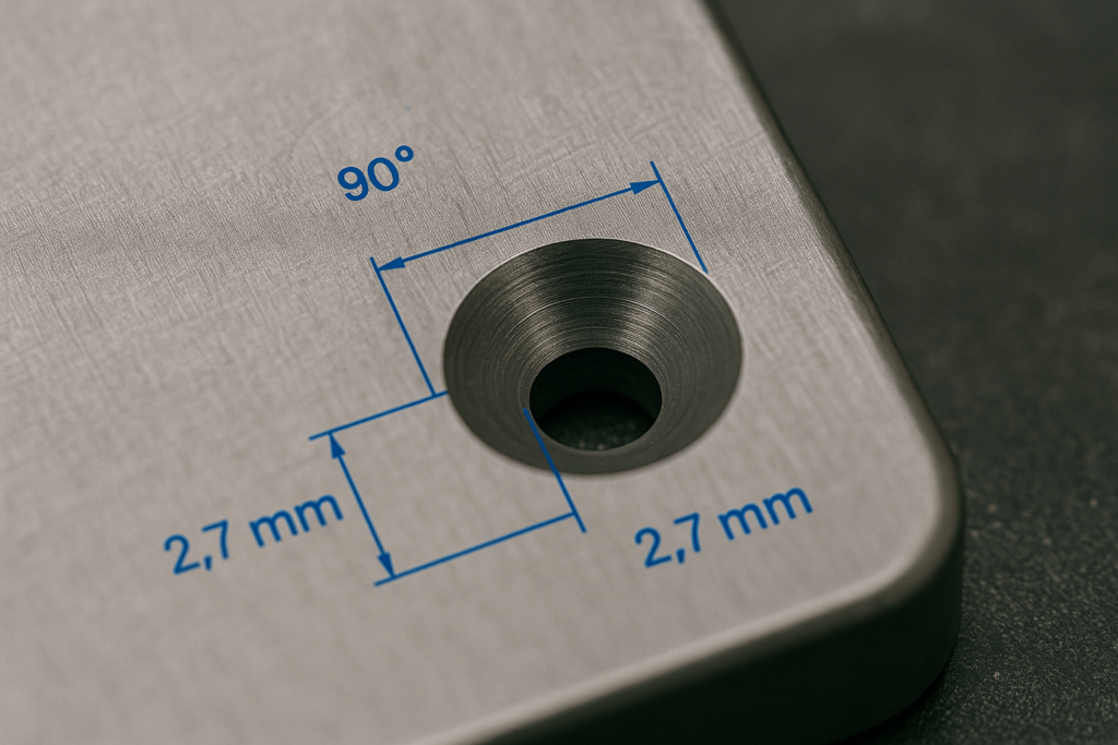
What angle should I use for a sheet metal countersink?

Use the angle that matches the screw head standard. In many projects, inch-series flat head screws use 82°, while metric flat head screws use 90°.

Can I use a formed countersink in thin sheet metal?

It depends on the material and thickness. For very thin sheet metal, machining is often safer because aggressive forming may cause thinning, distortion, or cracking.

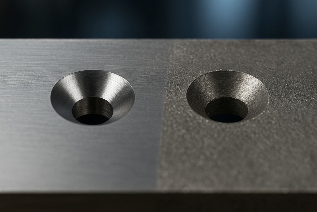
How do I choose between machined and formed countersinks?

If appearance, flushness, and tighter control are more important, machining is usually the better choice. If production volume is large and the material forms well, forming may reduce unit cost.

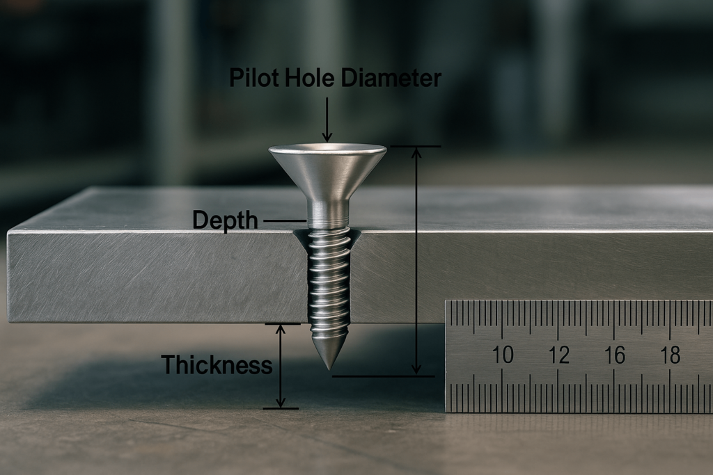
Why is the screw head still proud after assembly?

Common causes include the wrong countersink angle, insufficient depth, burrs, or coating buildup after finishing.

Should flushness be checked before or after coating?

For painted or powder-coated parts, the final flushness should be checked after finishing, especially when the countersunk seat is visible or functionally critical.

Custom Sheet Metal Countersink Services from YISHANG

YISHANG Metal Products Co., Ltd. is a custom metal fabrication factory with more than 26 years of experience in sheet metal parts, metal cabinets, display racks, and metal frames for wholesale and OEM/ODM projects.

We work with materials such as:

  • stainless steel 304 / 316

  • low carbon steel

  • galvanized steel

  • aluminum

  • copper

  • brass

Our manufacturing capabilities include:

  • sheet metal laser cutting

  • sheet metal bending

  • deep drawing

  • stamping

  • welding

  • CNC machining

  • surface finishing

  • design support

  • prototyping

  • assembly

  • packaging

  • quality inspection

  • shipping

If your project requires custom countersunk sheet metal parts, our team can help review the design, evaluate manufacturability, and support sampling before volume production.

We'd like to work with you

If you have any questions or need a quote, please send us a message. One of our specialists will get back to you within 24 hours and help you select the correct valve for your needs.

Get A Free Quote

All of our products are available for sampling