
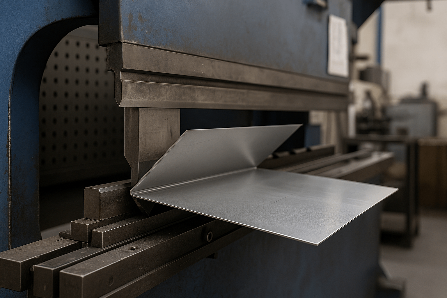
For industrial designers, engineers, and overseas procurement professionals, precision in a CAD model is a baseline. The true challenge lies in transforming digital accuracy into manufacturable, repeatable parts—particularly in custom sheet metal fabrication. A central question arises before production begins: will the part formed from a flat sheet meet final dimensional tolerances?
For wholesale buyers, importers, and supply chain managers, errors in flat pattern development lead to costly issues: scrapped inventory, shipping delays, and dimensional mismatches in final assemblies. This article clarifies how mastering sheet metal design formulas protects your cost structure and timelines—without diving into unnecessary math.
Phase 1: Why Simple Geometry Fails in Sheet Metal Design
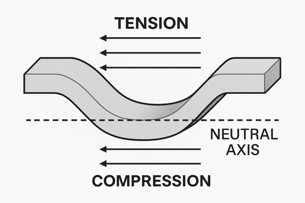
A common mistake in sheet metal design is assuming you can simply sum flange lengths to calculate total material needed. But bending is not a flat process—the material changes shape:
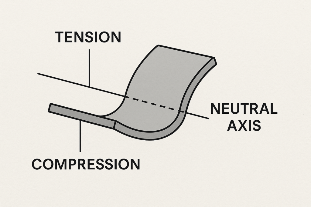
Outer edge: stretches under tension and becomes slightly thinner
Inner edge: compresses and thickens slightly
Neutral axis: remains the same length, but shifts from center toward the inner radius
✅ Why it matters: If you ignore the shift of the neutral axis, your flat pattern dimensions will be off—even if your CAD model looks perfect.
📌 [Tip: Add a labeled diagram showing tension, compression, and neutral axis.]
Phase 2: Sheet Metal Design Formulas — The Four-Pillar Framework
With bending physics understood, use this proven calculation structure:
K-Factor Calibration
Choosing a Calculation Method (BA or BD)
Tooling Constraints
Flat Pattern Output Calculation
Each step builds consistency into your parts—and minimizes surprises during production.
Pillar 1: The K-Factor (Neutral Axis Positioning)
The K-Factor is the ratio between the distance to the neutral axis and the total material thickness:
Formula: K = t / T
t = Distance from inside face to neutral axis
T = Total material thickness
Common values by material:
| Material | Bend Type | Typical K-Factor |
|---|---|---|
| Soft Aluminum | Sharp Radius | 0.33–0.38 |
| 5052/6061 Aluminum | Normal Radius | 0.38–0.42 |
| Mild Steel | Normal Radius | 0.42–0.46 |
| Stainless Steel | Normal Radius | 0.44–0.48 |
| Any (Large Radius) | >3× Thickness | 0.48–0.50 |
🔧 YISHANG Tip: We back-calculate K-Factors from sample bends using actual production tooling—ensuring real-world flat pattern accuracy.
Pillar 2: Two Methods — BA or BD
Once you know the K-Factor, choose your calculation method:
| Method | Best For | Formula Summary |
| BA | Flange-based part design | BA = (π × A / 180) × (IR + K × T) |
| BD | Controlling overall part dimensions | BD = 2 × OSSB − BA, with OSSB = tan(A/2) × (IR + T) |
💡 Pick the method that matches your CAD workflow or drawing reference points.
Pillar 3: Tooling Constraints
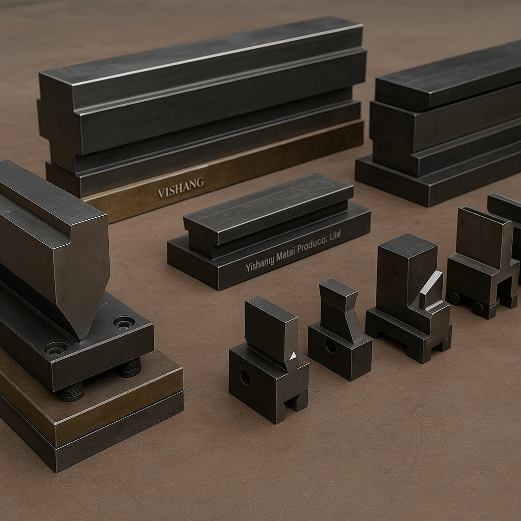
The inside bend radius (IR) is defined by press brake tooling. It directly affects part shape, strength, and springback.
Standard rule: V-die opening ≈ 8× material thickness (for steel)
Design reminder: Avoid specifying IR values that tooling can’t achieve—cracking or warping may occur
📌 Check with your sheet metal partner for tooling capability charts.
Pillar 4: Final Flat Pattern Length (FPL)
Now calculate the flat pattern:
Using BA: FPL = Flange1 + Flange2 + BA
Using BD: FPL = (Outer Dim1 + Outer Dim2) − BD
Example Case:
Material: 2mm steel
IR: 2.5mm
K: 0.44
Flanges: 50mm
📏 Result: FPL = 192.618mm — verified using tested K-Factor and consistent tooling inputs.
Phase 3: Don’t Forget Springback
After bending, the metal tends to relax slightly—this is known as springback. It’s especially common in high-strength materials.
Springback is affected by:
Material yield and thickness
Bend radius
Tooling method (air bend vs coining)
Control options:
Overbend slightly to offset recovery
Coining to minimize memory effect
Use allowances in design drawings
📌 Always test with your actual production batch—springback varies significantly by lot.
Common Mistakes to Avoid
❌ Specifying tight radii — leads to cracking and tool wear; keep R/T ≥ 1
❌ Placing holes too close to bends — use 3–4× thickness as clearance
❌ Ignoring grain direction — bending across grain minimizes fracture risk
❌ Neglecting tolerance stacking — always identify critical dimensions
Phase 4: Use a Sheet Metal Calculator Online
Tools like a sheet metal bending calculator help you input:
Material thickness
K-Factor
Bend radius & angle
These calculators output BA, BD, and FPL—perfect for validating your design before cutting.
💡 Tip: Search “how to calculate flat pattern for bending” for top-rated tools.
Final Thoughts: From Math to Manufacturing
Good design is measurable. Accurate sheet metal formula application transforms digital drawings into predictable production results.
At YISHANG Metal Products, we provide:
✅ Custom sheet metal parts for wholesale/OEM buyers
✅ Design-to-production support for global projects
✅ Flat pattern validation before fabrication
FAQ: Sheet Metal Design Formulas
Q1: Can I rely on CAD software’s default K-Factor?
Not for final production. Default values are for general use—real tooling, radius, and material may vary.
Q2: Is springback always predictable?
No. It depends on material, bend method, and thickness. Always test.
Q3: Do thicker materials behave the same?
No. They need wider radii and exhibit more springback.
Q4: Can I design a zero-radius bend?
Not realistically. It leads to stress cracks. Use appropriate minimum bend radius.