
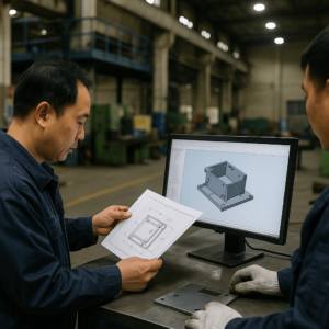
Introduction: From CAD File to Catastrophe
For procurement managers and wholesale buyers, flawed sheet metal design isn’t just a technical glitch—it threatens delivery schedules, consistency, and cost control. A metal assembly that looks perfect in CAD can become a production liability, plagued by fitment issues, delays, and inconsistent quality across large-scale orders.
These issues disrupt supply chains, inflate labor costs, and elevate Total Cost of Ownership (TCO), undercutting long-term profitability. This guide outlines a practical framework to catch these risks early. We’ll expose five design “sins” that often derail sheet metal assembly success—and offer practical hacks to ensure your custom sheet metal fabrication remains scalable, cost-effective, and production-ready.
Sin #1: The Original Sin – Designing in a Silo
Symptom: Engineering Revisions and Delays
The project kicks off but quickly stalls. The manufacturer returns the “finalized” file with modification requests due to tooling conflicts or tolerance mismatches.
That first delay snowballs into broader production setbacks, threatening your shipping commitments. For procurement professionals, this signals an unstable, unpredictable supply chain.
Root Cause: Isolated Design Decisions
These disruptions often stem from siloed development where design engineers operate without manufacturing feedback. As a result, what looks great on-screen doesn’t align with fabrication realities.
Hack #1: Adopt an “Assembly-First” Mindset
Minimize downstream risk by embedding an Assembly-First philosophy rooted in DFMA (Design for Manufacturing and Assembly). This ensures engineering decisions align with real-world shop floor constraints.
In Practice: Design Collaboration with Your Manufacturer
Collaborate with a fabricator like YISHANG early in the design phase—not as a vendor, but as a technical partner. For example, avoid specifying custom bend radii that require special tooling. Instead, use standard radii (typically 0.030 inches or equal to material thickness) to streamline setup, reduce cost, and simplify production planning.
Procurement Risk: Missed Milestones & Change Orders
Early manufacturability alignment prevents rework loops, redesign costs, and last-minute disruptions. That translates into better control of your delivery schedule and reduced TCO.
Sin #2: The Sin of Complexity – Designing “Dumb” Parts
Symptom: High Part Count, High Assembly Costs
The design includes many flat plates and brackets, all welded or fastened together. While unit prices seem acceptable, total project cost grows due to excessive handling, inspection, and assembly.
Root Cause: Over-Segmentation & Redundant Operations
Relying on basic cut-and-weld strategies leads to complex assemblies, higher BOM count, and more process variables.
Hack #2: Engineer Smarter, Multi-Functional Components
Reduce costs and lead time through part consolidation. Look for ways to combine structural and functional roles into fewer components.
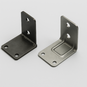
In Practice: Replacing Weldments with Formed Geometry
Instead of fabricating four pieces and welding them together, one bent component might suffice. A case in point: a four-part axis stop re-engineered into a single formed piece eliminated six operations, reduced QC points, and cut total cost by 46%.
In Practice: Use Geometry to Add Strength
Build structural integrity into the form:
- Hems for edge reinforcement
- Ribs to reduce material usage while boosting stiffness
- Stamped Gussets to strengthen corners without welding
Procurement Risk: Longer Assembly Time & Higher BOM Overhead
Fewer parts mean easier sourcing, less packaging, and faster builds. Lighter assemblies reduce shipping cost, and integrated strength improves product life span.
Sin #3: The Sin of Manual Labor – Designing for Fixtures, Not Flow
Symptom: Heavy Fixture Dependence
Skilled operators must manually align parts with jigs—introducing variability and slowing throughput. Production struggles to scale efficiently.
Root Cause: Lack of Built-In Alignment
Designs lacking self-location features depend on external fixtures, increasing labor and reducing repeatability.
Hack #3: Make Parts Self-Locating
Design components that align themselves during assembly. This principle enables high-volume, low-variance production.
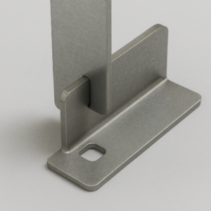
In Practice: Tab-and-Slot Precision Alignment
Tab-and-slot joints function like a 3D puzzle. Add 0.007-inch clearance on all sides (for steel) to enable easy insertion without slop. These eliminate fixture needs and reduce assembly errors.
In Practice: Prevent Assembly Errors with Poka-Yoke
Use geometric differentiation (e.g., asymmetric tabs or variable slot widths) to prevent incorrect part orientation. This reduces rework and increases consistency.
Procurement Risk: Labor Cost Spikes & QA Failures
Parts that self-align require less skilled labor and produce fewer assembly defects. The result: stable per-unit costs and scalable order fulfillment.
Sin #4: The Sin of Determinism – Fighting Manufacturing Reality
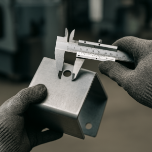
Symptom: Parts Pass QC but Don’t Fit
Components meet tolerance specs but still don’t assemble properly. Misaligned holes, over-constraint, or dimension creep cause delays.
Root Cause: Ignoring Tolerance Stack-Up
Minor manufacturing variances accumulate, particularly across bends or in multi-part mating assemblies. Responding with tighter tolerances inflates cost without solving the root problem.
Hack #4: Design to Absorb Variation
Allow controlled flexibility rather than over-constraining.
In Practice: Add One Slot, Not Two Holes
Pair a round locating hole with an elongated slot. The hole locks placement; the slot absorbs length variation. This avoids stress build-up or misalignment.
In Practice: Use Functional Tolerancing
Match tolerance bands to function:
| Feature Relationship | Typical Tolerance (Steel/Aluminum) |
|---|---|
| Hole to Hole (same plane) | +/- 0.005 in. (+/- 0.127mm) |
| Bend Angle | +/- 1 degree |
| Bend to Hole/Feature | +/- 0.015 in. (+/- 0.381mm) |
| Feature across 2+ Bends | +/- 0.030 in. (+/- 0.762mm) |
Procurement Risk: Rework, Scrap & Delays
Function-first tolerancing avoids overdesign and reduces misalignment issues—lowering rework cost and protecting production throughput.
Sin #5: The Sin of the Afterthought – Forgetting the Finish Line
Symptom: Painted Parts No Longer Fit
Tabs no longer fit. Holes close up. Post-coating, parts that once assembled cleanly are now unusable.
Root Cause: Overlooking Dimensional Impact of Coatings
Surface treatments—especially powder coating—add thickness that affects fits and tolerances. Designs must anticipate this added layer.
Hack #5: Account for Finishing Early
Integrate coating considerations during initial CAD modeling.
In Practice: Adjust Dimensions for Coating Buildup
Powder coating adds 0.002–0.005 inches per side. For tab-and-slot fits involving four coated surfaces, clearance loss reaches 0.020 inches. Increase slot widths accordingly.
In Practice: Use Pre-Plated Materials When Possible
Design to avoid welding where possible. This enables the use of pre-galvanized or pre-coated material, which improves finish quality and shortens process flow.
Procurement Risk: Post-Processing Delays & Assembly Failure
Accounting for coating during design prevents end-stage failures. Coating-aware specs also simplify production, reduce downtime, and improve delivery reliability.
Conclusion: A Buyer’s Design Readiness Checklist
Before approving your next metal fabrication project, audit your design using these five checkpoints:
- Consolidation: Can multiple parts be merged?
- Self-Fixturing: Are components alignment-friendly?
- Labor Efficiency: Does the design avoid jigs and fixtures?
- Tolerance Strategy: Are tolerances functional, not just tight?
- Finish-Aware Design: Are coatings accounted for dimensionally?
This checklist ensures your design is production-ready, scalable, and built to reduce downstream risks.
For wholesale buyers seeking long-term reliability, these principles are essential. Request a free DFM consultation from YISHANG and start optimizing your sheet metal assemblies today.
Frequently Asked Questions (FAQ)
Q1: When is a tab-and-slot design a bad idea? While efficient, it’s not ideal for exterior-facing parts where seams must remain invisible. It may also complicate assemblies with extremely small tolerances.
Q2: How do I calculate clearance for powder-coated assemblies? Add the total coating thickness (typically 0.008–0.020″) to your standard mechanical clearance (0.007″ per side).
Q3: What’s the most common mistake with tolerance stack-up? Applying tight tolerances across bends. Variances in press brake angles create misalignment—focus tolerance where fit matters most.
Q4: Can I use snap-fits in sheet metal design? Yes, especially with spring steel or aluminum. Ensure proper bend radius and flex limits to avoid fatigue cracking.
