The Premise: A Hinge Isn't a Component, It's a System That Defines Your Product's Value
In sheet metal fabrication, long-term product value is often determined by the smallest details. Treating the hinge as a simple component typically shows up later as door sag, IP leak re-tests, and warranty claims.
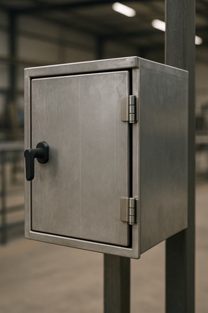
Consider a high-end outdoor electronics enclosure that fails its IP67 water ingress test after six months. The root cause wasn’t a faulty seal, but a sagging door due to a hinge choice that neglected the physics of the system. For a wholesale purchaser, this translates directly to warranty claims and damaged market reputation.
A hinge is the heart of a complex mechanical system, an interplay between the panel, frame, fasteners, and its environment. Choosing the right hinge is an engineering decision that impacts everything from supply chain reliability to final product performance. This guide offers a first-principles approach to sheet metal hinge selection, shifting the focus from reactive part-picking to proactive system design.
At YISHANG, we treat hinges as systems and validate choices across the full product lifecycle—practical, testable, and tied to measurable performance.

Step 1: Define the Operational Mandate
Before diving into hardware, we must first define the system’s mission. This “Operational Mandate” is the foundational document for our design, establishing clear engineering requirements and core design specifications. A flawed mandate guarantees a flawed outcome, impacting both cost and quality.
Kinematic Signature
First, define the system’s Kinematic Signature—its specific movement characteristics. This goes beyond a simple hinge range of motion; it defines the end-user experience.
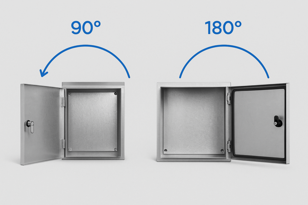
Does the application demand a full 180° opening angle for complete access, or is a hard stop at 90 degrees required for safety? A poorly planned opening angle can lead to costly collisions. Quick check: swing clearance ≈ door thickness + bend radii + gasket stack-up; ensure minimum gap to adjacent flanges and fasteners.
More subtly, what is the desired feel? A premium product might require the smooth motion of a damped hinge. A heavy industrial guard may need a simple, free-swinging pivot. This detail directly influences the perceived quality of your final product.

Access Protocol
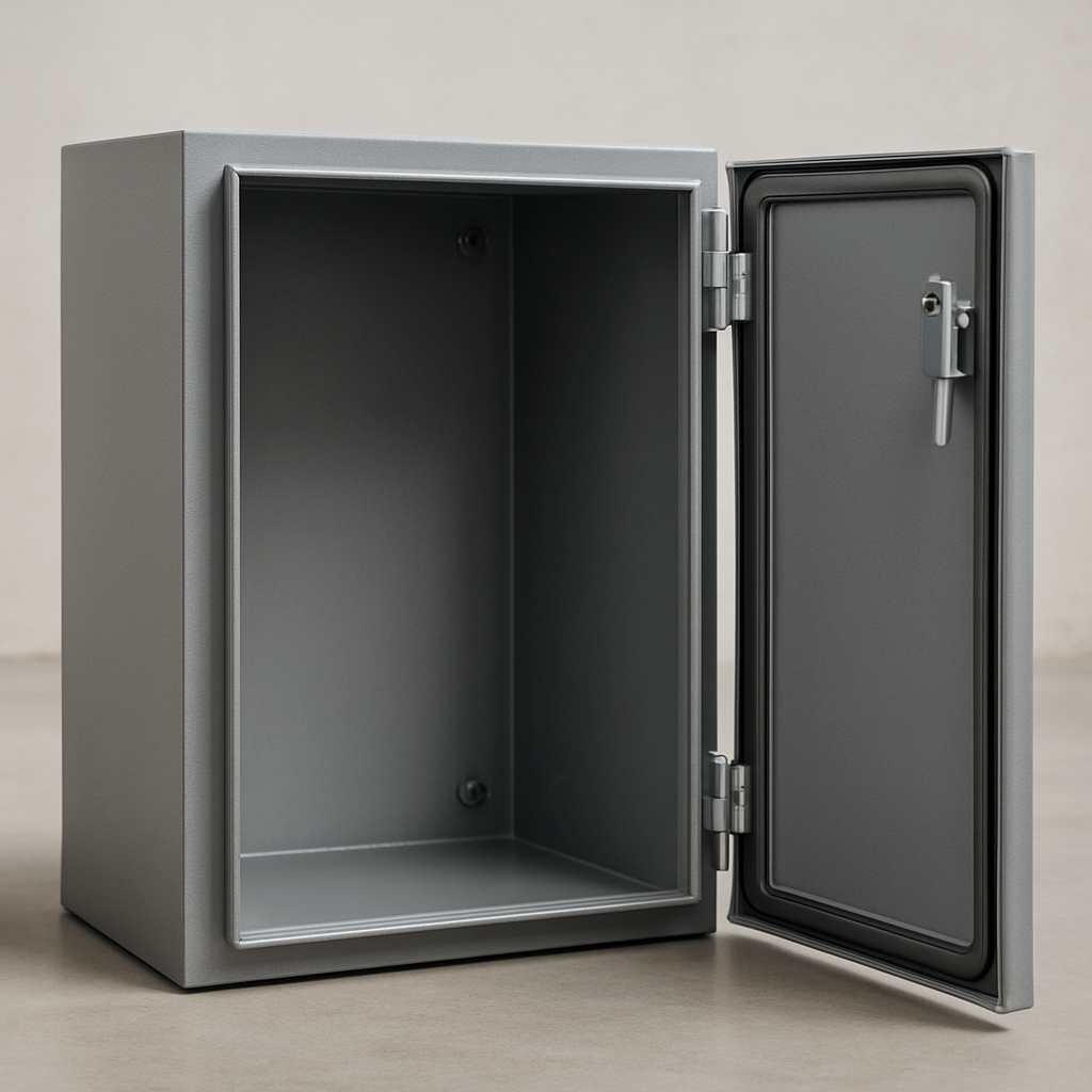
Next, establish the Access Protocol. How will the panel or door be interacted with? For frequent maintenance, a removable panel hinge, like a lift-off hinge, is essential for efficiency.
This choice brings follow-up considerations: is a left-hand or right-hand configuration needed? (Convention: viewed from the service side, hinges on the left = left-hand door.) How critical is precise realignment? Use dowel/step reference holes or pilot features so lift-off/flag hinges can be removed and reinstalled without losing gasket compression or latch alignment. For modular systems, this is a feature; for high-precision doors, it can be a bug.
For high-security applications like cash-handling machines, a security hinge with non-removable pins is non-negotiable. Prioritizing serviceability over security is a common design error that can create significant vulnerabilities.

Lifecycle Demand
Finally, quantify the Lifecycle Demand. A high-use product may endure tens of thousands of cycles, demanding exceptional durability and wear resistance.
The specified hinge cycle life must be supported by empirical data. For reference, some architectural hardware standards (like BHMA) test hinges for up to 2.5 million cycles.
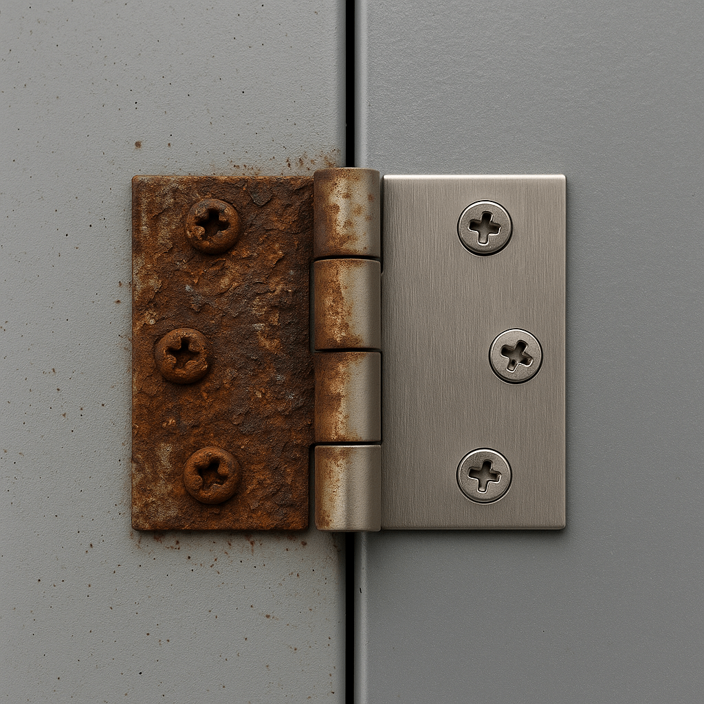
Conversely, an access panel on stationary equipment might only be opened a few dozen times. Here, long-term corrosion resistance is more critical than fatigue from load cycles. A real-world example our team consulted on involved hinges on a backup generator. After three years in a coastal environment, they had seized due to corrosion, a failure of material selection, not cycle life.
Cycle bands (quick map):
| Use Frequency | Typical Cycles | Recommended Hinge/Interface | Salt Spray Target |
|---|---|---|---|
| Low | < 500 | Plain bearing or rolled knuckle | ≥ 48 h |
| Medium | 5k – 20k | Bushed or sintered-bearing knuckle | ≥ 96–240 h |
| High | > 100k | Ball-bearing or polymer bushed; hardened pin | ≥ 240–500 h |

Step 2: Quantify the Forces
With the mandate defined, we move to the physics. A hinge system is in a constant battle with forces. A failure to accurately quantify these forces is a primary reason for system failure, leading to unforeseen costs and delays.
The Gravity of the Situation: Conquering Moment Load
The most dangerous force is not the direct weight of the door, but the moment load (or torque) it generates. This turning force is what causes the dreaded door sag.
A precise hinge load calculation is essential. You can approximate it with a simple principle: Moment = (Panel Weight × ½ Panel Width).
Example: a 12 kg door with its center of mass ~450 mm from the hinge line creates ≈ 12 × 9.81 × 0.45 ≈ 53 N·m of torque at the hinges. If accessories shift the center of mass closer to the latch side, the ½-width rule no longer holds—recalculate with the true CG distance. In multi-hinge layouts, load is not shared evenly; the top hinge typically carries the highest load.
Quick RFQ calc fields: mass (kg), door width (mm), CG distance to hinge line (mm), planned hinge count & spacing (mm), opening angle (°), environment (indoor/outdoor/coastal), target cycles.
The critical takeaway is that hinge spacing is your most powerful tool. Often, a designer’s first instinct is to specify a stronger, more expensive hinge. A more effective and cost-effective solution is often to simply increase the distance between the hinges.
| Hinge spacing (mm) | Relative force on top hinge (%) |
| 300 | 100 (baseline) |
| 600 | ~50 |
| 900 | ~33 |
| 1200 | ~25 |
Assumptions: two hinges, static load, evenly spaced. Real assemblies skew higher on the top hinge.
As the table shows, doubling the spacing can nearly halve the force. This simple analysis can prevent costly over-engineering.
Beyond Static: Accounting for Dynamic & Shock Loads
Real-world conditions are dynamic. A door on a utility vehicle will face constant vibration and shock exposure. An external door can be caught by wind, creating a massive dynamic load on hinges.
These shock loads can exert forces many times greater than the static weight. Therefore, applying a safety factor is a critical engineering judgment. For a stable indoor cabinet, a factor of 1.5 might suffice. For a system subject to heavy vibration, a factor of 3.0 to 5.0 may be necessary. Quick guide: indoor cabinets 1.5–2.0; outdoor wind-exposed 2.0–3.0; vehicle/high-vibration 3.0–5.0—and validate per IEC 60068 or an equivalent vibration/shock protocol.
Step 3: Map Viable Hinge Architectures
Now we can explore specific hardware. We approach this by mapping our design constraints to proven hinge design philosophies, or “architectures.” Each represents a different solution with its own set of trade-offs relevant to your procurement decisions. Common hinge types include butt, torque/friction, and spring hinges; the architectures below map these choices to system needs.
Distributed Load Architectures
For long, heavy, or thin panels requiring precise alignment, a Distributed Load Architecture is superior. The classic example is the piano hinge, or continuous hinge.
This architecture distributes the load along the entire length of the panel, increasing rigidity. Piano hinge applications are ideal for large enclosure doors or server racks where even minor sagging can cause issues.
Their continuous nature also makes them an excellent choice for applications requiring EMI/RFI shielding. The trade-off is that they are not suitable for quick panel removal and can be time-consuming to install.
Modular & Removable Architectures
When the Access Protocol demands frequent removal, a Modular & Removable Architecture is necessary. This category is led by the lift-off hinge (or flag hinge).
Their two-part design allows a door to be lifted off its frame without tools, epitomizing ease of access. These are the go-to solutions for machinery guards and electrical panels.
The trade-off is in security and environmental sealing. Their design can have more “play” than a fixed hinge, potentially compromising gasket compression in a high-IP-rated enclosure.
Aesthetically Integrated Architectures
When the design mandate prioritizes a clean appearance and enhanced tamper resistance to increase product value, an Aesthetically Integrated Architecture is the only option. This is the domain of the concealed hinge for metal.
When the door is closed, the hinge is completely hidden, providing a high-end, architectural look. This can be a key differentiator in a competitive market.
However, this comes with engineering trade-offs. An invisible hinge installation requires a mortise to be created in the door and frame, adding complexity and cost to fabrication. They also typically have a lower load capacity.
| Architecture | Primary Strength | Key Trade-Offs | Best Fit Scenario |
| Distributed Load | Even load distribution, high rigidity | Not removable, slower install | Long/heavy doors, EMI shielding |
| Modular/Removable | Fast, tool-less removal | Lower security, less sealing | Frequent service access panels |
| Aesthetically Integrated | Invisible when closed, integrated look/tamper resistance | Higher cost, complex install | High-end enclosures, architectural designs |
Step 4: Analyze the System's Weakest Links
Selecting the architecture is a major milestone. Now we must analyze the system’s weakest links. In our experience at YISHANG, these are often not the hinge itself, but the interfaces.
The Material Interface: Preventing Galvanic Corrosion
One of the most insidious failure modes is galvanic corrosion. This occurs when two dissimilar metals are in contact in the presence of an electrolyte.
A classic mistake is pairing a stainless steel hinge with an aluminum panel in an outdoor environment. This creates a galvanic cell, and the aluminum panel will corrode.
Galvanic corrosion prevention is a matter of smart material selection. The first principle is to use compatible materials. When not possible, isolate them using non-conductive washers. Referencing standards like ASTM B117 for salt spray testing is a crucial step.
Environment × material pairing (risk snapshot):
| Environment | Al–SS | Al–CS | SS–CS |
| Indoor | Low–Medium | Medium | Low |
| Industrial/Urban | Medium–High | High | Low–Medium |
| Coastal/Marine | High | Very High | Medium |
Isolation methods: non-conductive washers/gaskets, barrier coatings/paint, polymer or composite bushings/spacers.
The Fastener Junction: The Unsung Hero or Villain
The method used to attach the hinge is as critical as the hinge itself. The choice of hinge fastener selection defines the joint strength.
Standard screws offer serviceability but can suffer from vibration loosening. Rivets provide excellent vibration resistance but are permanent.
A weld-on hinge creates the strongest connection but introduces thermal stress. In thin sheet metal, specialized fasteners like rivet nuts or clinch nuts (PEM nuts) are often a superior choice.
Fastener tips: maintain edge distance ≥ 2× hole diameter (or ≥ 3 mm minimum); specify torque/prevailing-torque where applicable; compare anti-loosening strategies (nylon insert nuts, all-metal locknuts, thread-locking compound, riveting) against your serviceability needs.
The Sheet Metal Itself: Is Your Foundation Solid?
Finally, we must analyze the foundation: the sheet metal. A heavy-duty hinge is useless if mounted to a thin, unsupported panel.
The forces on the hinge will be transferred to the panel, causing material deformation. The sheet metal thickness for hinges must be sufficient to handle the loads.
When a thicker panel isn’t feasible, reinforcing sheet metal is essential. This can be done by adding backing plates or designing stiffening features directly into the part.
Reinforcement cheatsheet: use local doublers/backing plates ≥ panel thickness; add flanges/beads to increase section modulus near the hinge line; if using weld-on hinges on thin sheet, control heat input and fixture to prevent HAZ distortion and door twist.
Step 5: Beyond the Component: A Partnership in Manufacturability (DFM)
For hinges, DFM priorities drive both cost and risk. It’s about finding a partner who can add value and reduce risk. This is where Design for Manufacturability (DFM) becomes paramount. For hinges specifically, focus on: standardized hole sizes/pitch, stocked PEM nut specs, whether countersink/counterbore is truly required, hinge-to-edge minimum distances, and weld distortion compensation/tolerance stack-up around the hinge line.
An experienced fabricator like YISHANG sees the entire manufacturing process. We provide critical feedback before production begins. For example, a slight change in hinge placement might simplify tooling and reduce cost.
We might recommend changing from a welded hinge to a bolt-on design to eliminate heat distortion. Or, we might analyze tolerances and advise where they can be loosened to improve production speed. This collaborative DFM process transforms the relationship from a transaction to a strategic partnership.
Step 6: The Prototyping and Validation Phase
Theory can only take a design so far. Prototyping and validation are critical. Skipping this step is a false economy that often leads to costly tooling changes.
A 3D printed model is a low-cost first step to verify the Kinematic Signature. It allows you to check the true swing clearance and ergonomics.
Following this, fabricating prototype assemblies is essential. These should be used for rigorous testing that simulates real-world conditions, including static load tests and cycle tests. This validation provides the empirical data to prove your design is sound.
Validation checklist (sample): static hold/load-to-failure; cycle life to spec; vibration/shock per IEC 60068 (or equivalent); salt spray per ASTM B117 for target hours; seal/IP leakage check; drop/impact if applicable. Define clear pass/fail thresholds before testing.
Acceptance snippet (one-page): Item/Rev; Hinge PN/spec; Test conditions; Cycles achieved; Max deflection; Fastener torque audit; Corrosion hours; IP leak result; Pass/Fail; Corrective actions.
Conclusion: From Sourcing Risk to Engineered Certainty
The journey from a CAD screen to a reliable hinged assembly is a process of systematic engineering. For wholesale buyers, this process is also about risk mitigation.
By embracing a first-principles, system-level mindset, you transform the process from a sourcing gamble to a predictable manufacturing outcome.
The framework is clear: Define the Mandate -> Quantify the Forces -> Map the Architecture -> Analyze the Weakest Links -> Optimize for Manufacturing -> Prototype and Validate. This methodology shifts sheet metal hinge selection from a source of potential failure into an opportunity to add tangible value to your product.
The result is a solution that performs its mission flawlessly for its entire lifecycle.
Frequently Asked Questions (FAQ)
1. What is the most common cause of hinge failure in sheet metal parts? The most common failure is not the hinge breaking, but door sag. This is almost always caused by underestimating the moment load and having insufficient spacing between the hinges.
2. How many hinges should I use on a door? While a general rule is “one hinge for every 30 inches of height,” an engineered approach is better. For most doors, two hinges are sufficient if spaced far apart. A third hinge can prevent bowing on tall panels.
3. Can my hinge choice affect the cost of the sheet metal part itself? Absolutely. A simple butt hinge may only require punched holes. A concealed hinge requires a secondary operation like milling, adding significant cost. An experienced supplier can advise on the most cost-effective solution.
4. What is the difference between a 304 and 316 stainless steel hinge? 316 stainless steel contains molybdenum, giving it superior resistance to chlorides. For any application in a marine or chemically harsh environment, 316 is the mandatory choice. For general-purpose applications, 304 is usually sufficient.
5. Besides corrosion, what is another “invisible” killer of hinge systems? Vibration. In mobile applications, constant vibration can cause threaded fasteners to loosen. Mitigate with proper torque, nylon-insert or all-metal locknuts, thread-locking compounds, or rivets where serviceability is not required.
6. What are recommended hole sizes and edge distances near hinges? As a rule of thumb, keep edge distance ≥ 2× hole diameter (≥ 3 mm minimum) and maintain consistent hole patterns to support PEM/rivet-nut installation and load paths.
7. How do I prevent galvanic corrosion in mixed-metal assemblies? Choose compatible pairings where possible; otherwise, electrically isolate (non-conductive washers/gaskets, polymer bushings), and specify barrier coatings. For coastal environments, prefer 316 SS hardware and higher salt-spray targets.

