
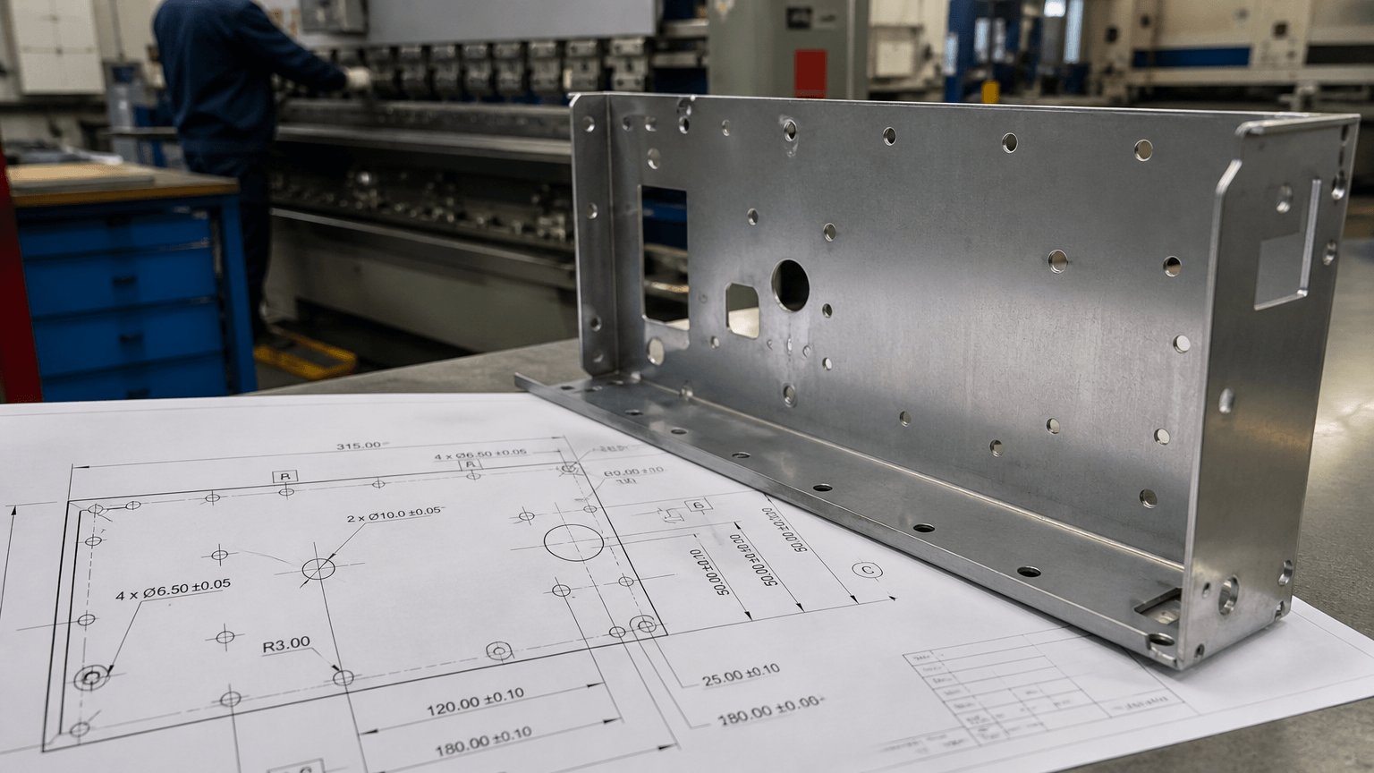
Direct answer: Tighter tolerances mean less permitted variation around a nominal dimension. If an enclosure door must close without rubbing or a hole pattern must align with a mating frame, a narrower limit may be justified. It does not, however, automatically make the whole part more accurate or improve the product.
For custom sheet metal parts, the useful requirement is the one that survives the full route: material and thickness, cutting, bending, welding, finishing, assembly, and inspection. The right limit depends on the feature’s function, the process sequence, batch conditions, and measurement method—not on a single universal value.
What tighter tolerances mean on a sheet metal drawing
When an OEM buyer sees a narrow limit on a drawing, the key question is whether the finished interface can hold it through the proposed route—not whether a machine display shows enough decimal places.
A tolerance defines the allowed zone around a nominal dimension. For example, an illustrative dimension of 100 mm ±0.30 mm permits more variation than 100 mm ±0.10 mm. These examples explain the principle only; neither value is a universal benchmark for sheet metal fabrication.
Accuracy is the closeness of the produced feature to its nominal target. Precision commonly describes how closely results agree with one another, although it should not be used as a substitute for accuracy. Repeatability is more specific: it describes consistency when the same process, equipment, setup, and conditions are used again. A process may repeat reliably while remaining consistently offset from nominal. Fit describes the relationship between mating parts, such as a cover and a metal enclosure opening, rather than the size of one isolated feature. Conformance is whether the measured result falls within the specified acceptance zone.
Geometric controls address more than size. Position controls where a feature lies in relation to datums. Flatness controls the form of a surface. Perpendicularity and parallelism control orientation. Profile can control a more complete boundary or surface relationship. Other controls, such as straightness or angularity, may be relevant to a particular interface. Tightening a size limit will not necessarily solve a position, orientation, or flatness problem.
Choose the feature that carries the function
Consider an enclosure door that must close over a bent panel or a hole pattern that must line up with a mating frame. In these cases, the important requirement may be the relationship between features—not the narrowest possible limit on every dimension. Start with the product function and the tolerance stack-up between mating components.
Decision matrix: where to tighten tolerances and what to verify
| Functional feature | Potential control | Main risk | Verification |
|---|---|---|---|
| Mating holes or slots | Size plus position or profile | The opening is acceptable, but the pattern does not align with the mating part. | Datum-based pattern inspection and a fit check. |
| Bend-to-hole relationship | Position or profile from formed datums | The flat blank is correct, but springback changes the hole-to-flange relationship. | First-article measurement on the formed part. |
| Enclosure door or cover | Opening size, flatness, profile, parallelism, or clearance | Several flanges accumulate variation and cause rubbing, gaps, or poor sealing. | Assembly fit check and measurements at defined points. |
| Frame squareness | Perpendicularity, parallelism, and diagonal relationship | Individual lengths pass, but the frame is out of square. | Datum-based geometric inspection and assembly validation. |
| Welded interface | Location, orientation, profile, or flatness of the finished interface | Heat distortion changes the relationship between parts that were correct before welding. | Fixture-controlled inspection and final assembly check. |
| Nonfunctional edge or clearance | Less restrictive dimensional control where function permits | Unnecessary limits add inspection and process effort without a product benefit. | Confirm the actual clearance, safety, or cosmetic requirement. |
Functional datums should represent how the part is located in the product and how it will be inspected. If assembly depends on a formed flange or welded face, a convenient flat-pattern edge may not express the real design intent. A Design Support review can help separate critical interfaces from dimensions that can remain less restrictive.
Use tighter tolerances selectively for features affecting movement, sealing, safety, interchangeability, or performance. Applying narrow limits to every drawing dimension can obscure priorities and make manufacturing and inspection harder without improving the finished product.
Why tolerances shift through fabrication
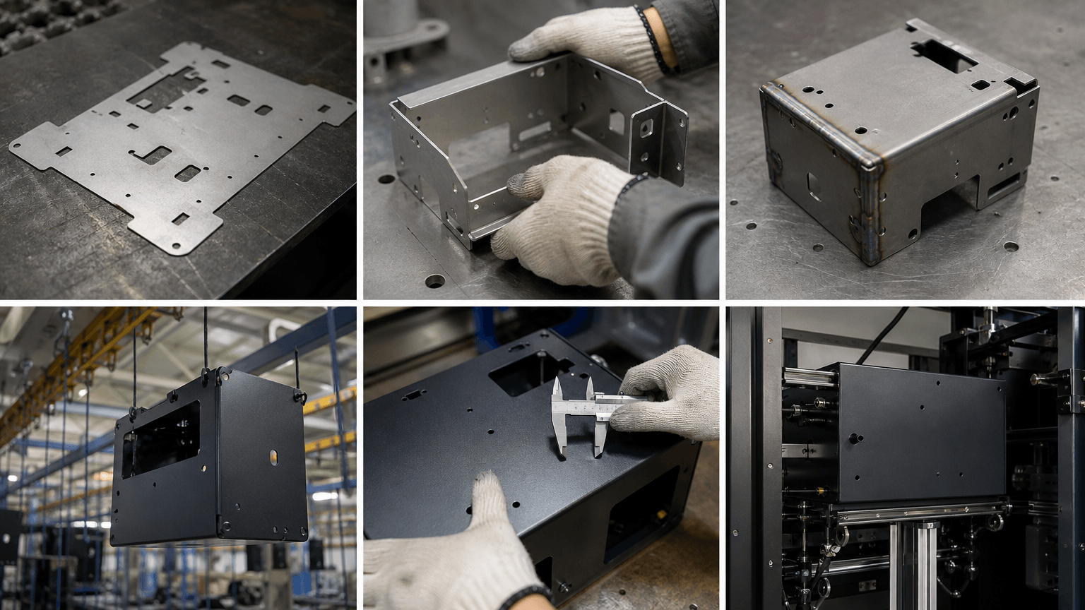
A flat cut profile is an intermediate state, not automatically the finished assembly. A hole may meet its flat-pattern requirement and still miss the mating component after forming, welding, coating, or assembly because each stage introduces a different source of variation.
- Laser cutting and CNC punching: Material grade and thickness affect thermal response, stiffness, and edge condition. Laser cutting introduces localized heat and may produce edge variation or dross where applicable. CNC punching depends on tool clearance, feature size and spacing, burr control, and tool wear. Both processes establish the flat pattern, but neither alone guarantees the final formed-part relationship. See Laser Cutting considerations before assigning tight cut-feature tolerances.
- Bending: Springback, bend allowance, tool selection, flange length, bend sequence, grain direction or forming behavior, and clamping affect the result. A hole located correctly from a flat edge can shift relative to a flange after forming. The critical requirement should therefore be defined from formed datums. The Metal Bending process review should focus on the finished relationship, not only the blank.
- Welding: Welding joins components and can introduce heat distortion and shrinkage. Clamping force, fixture stability, weld sequence, and the order of joining operations influence length, angle, flatness, and squareness after the assembly is released.
- Surface finishing: Finishing is a separate operation after fabrication. Coating buildup can reduce a clearance or change the fit of a covered interface. Masking may be needed on selected contact areas, holes, threads, or datum surfaces, depending on the finish and product function.
- Assembly: Several individually conforming sheet metal parts can still create a final fit problem when their variations accumulate in the same direction. Fastener clearance, fixture conditions, weld distortion, and finish thickness can all contribute to the assembly stack-up.
CNC milling or turning is a separate machining route, not an interchangeable version of sheet metal fabrication. It may suit a selected precision feature on a machined insert or serve as a secondary operation when the design and datums support that route. The machined feature then requires its own process review and inspection plan.
Repeatability comes from the controlled process
If a supplier points to equipment accuracy as the main evidence for a narrow requirement, ask how the actual feature behaves in the specified material, geometry, setup, and batch conditions. Equipment type is only one part of a capability review.
| Factor | Why it matters | Evidence to discuss |
|---|---|---|
| Material grade, thickness, and grain | They affect stiffness, thermal expansion, forming response, and cutting or welding behavior. | Material documentation, thickness control, and experience with the specified grade. |
| Part size, geometry, and feature location | Large panels, thin sections, asymmetric shapes, and features far from a locating reference can respond differently to heat and release forces. | A process review based on the actual geometry rather than a generic equipment range. |
| Parameters and tool wear | Cutting or forming settings, tool clearance, and wear can move features or change edge and bend results. | Setup records, parameter control, tool maintenance, and repeat measurements. |
| Clamping and fixture design | Uneven force, fixture movement, or operator-dependent setup can distort or reposition the part. | Fixture-control approach, setup instructions, and checks before release. |
| Batch size and production duration | Longer runs can expose tool wear, setup drift, or changes between batches, while larger quantities may require a more structured control approach. | Comparable first-article results, batch inspection records, and consistency data. |
| Thermal and measurement conditions | Cutting or welding heat, stabilization time, temperature during measurement, access, and measurement uncertainty can affect narrow requirements. | Defined measurement method, calibration and maintenance records, measurement locations, and environmental conditions. |
A machine’s advertised or nameplate accuracy does not establish finished-part capability or stable batch production. Calibration supports confidence in the equipment, but it should be combined with results from the same material, geometry, setup, and process route.
A capability index such as Cpk is meaningful only when the process is stable and the data represents the actual feature and production conditions. Ask for comparable process evidence rather than treating a general equipment specification as proof of batch consistency.
How narrower tolerance zones affect cost and lead time
During quotation, a narrow limit usually leaves less process margin for the specified characteristic. Depending on the feature and route, it may require additional programming and setup, dedicated tooling or fixturing, slower or staged processing, a secondary operation, more detailed inspection, and clearer nonconformance handling.
| Requirement change | Possible production effect | Buyer guidance |
|---|---|---|
| Tighter control on one mating feature | More careful setup and measurement, with potentially limited impact if the feature is accessible and stable. | Explain why that feature matters and leave unrelated dimensions functional. |
| Tighter bend, flatness, or position requirement | More forming trials, fixture work, sequence control, and final-part inspection. | Specify formed datums, fit conditions, and whether a prototype or first article is needed. |
| Tight limits across many features | Less process margin and greater exposure to sorting, rework, scrap, reduced yield, and schedule disruption. | Review the stack-up and identify the characteristics that are genuinely critical. |
| Detailed inspection and traceability | Additional measurement planning, reporting, records, sampling, and nonconformance administration. | Define the report format and acceptance method before quotation. |
The commercial effect depends on part complexity, batch size, material, tolerance location, and the inspection evidence required. A quotation should state these assumptions instead of applying an unexplained percentage surcharge to every tight tolerance.
The commercial review should identify the proposed process route, setup and tooling needs, inspection scope, rework treatment, and schedule assumptions. If the design is still flexible, tightening one mating feature, changing an assembly clearance, or improving the datum strategy may be more effective than narrowing every dimension.
If the project is still at the design stage, share a representative drawing, mating interface, material, and quantity assumptions for a tolerance and DFM discussion before the full batch is quoted.
Release and validate the requirement before batch production
Before approving a prototype or releasing production, connect the drawing requirement to the finished part and its assembly condition. A staged review is especially important when tolerances interact with bending, welding, coating, or multiple mating components.
- Define the drawing requirement: Show nominal dimensions, upper and lower limits, material grade, thickness, finish, critical characteristics, and relevant position, flatness, perpendicularity, parallelism, or profile controls.
- Establish functional datums: Select references that match how the part is located, assembled, and inspected. Do not use a convenient cutting edge when the real interface is a formed or welded surface.
- Share the mating condition: Provide mating parts, clearance or fit requirements, and tolerance stack-up information. An isolated dimension cannot fully describe an interface.
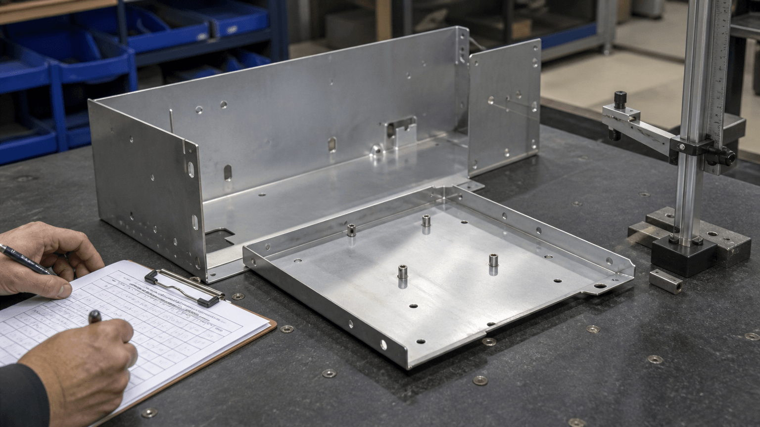
- Agree on verification: Define measurement locations, datums, inspection method, environmental conditions, reporting format, and how measurement uncertainty will be considered. Include calibration evidence appropriate to the measurement system.
- Validate a prototype or first article: Check the actual cut, formed, welded, finished, and assembled condition before batch release when springback, distortion, coating, or fit is involved. Record deviations and approve any drawing or process change through an agreed revision.
- Control production: Identify critical dimensions, inspection frequency, sample basis, nonconformance handling, material records, and batch traceability. First-article approval does not by itself prove that later production will remain consistent.
Bring the mating interface to the tolerance review
For an OEM or ODM tolerance and DFM review, provide:
- 2D drawings with nominal dimensions, tolerance limits, datums, geometric callouts, and critical features.
- 3D CAD files and mating parts or tolerance stack-up information where fit matters.
- Material grade, thickness, surface finish, coating, and masking requirements.
- Prototype quantity, expected batch size, and production schedule.
- Required inspection reports, fit checks, material documentation, and traceability expectations.
Yishang can review whether those requirements align with a proposed laser cutting, CNC punching, bending, welding, finishing, assembly, prototype-review, and batch-production route. This is a part-specific review, not a universal tolerance promise. Yishang has more than 26 years of custom metal manufacturing experience, exports to more than 50 countries, and holds ISO and RoHS certifications. Inspection planning and conformance evidence can be discussed through Quality Control.
Frequently Asked Questions
These questions address common sheet metal fit and sourcing decisions, from a narrow hole tolerance on a drawing to evidence that a supplier can maintain the requirement during batch production.
Is ±0.001 inch a normal or universal tighter-tolerance requirement for sheet metal parts?
No. ±0.001 inch, or 0.0254 mm, is not a universal sheet metal requirement. Whether such a narrow limit is necessary or realistic depends on the material, thickness, feature, part size, process chain, batch conditions, and inspection method.
Should every dimension on a sheet metal drawing receive a tighter tolerance?
No. Tighten dimensions and geometric controls that affect fit, movement, sealing, safety, interchangeability, or performance. Leave nonfunctional features less restrictive when the product function permits it.
Why can a laser-cut hole be acceptable in the flat blank but create a fit problem after bending or welding?
Cutting controls the hole in the flat pattern. Bending can introduce springback and change the hole-to-flange relationship, while welding can add heat distortion and shrinkage. The finished relationship must be checked from formed or assembly datums.
Do stainless steel and aluminum require different tolerance planning?
Often, yes. Stainless steel fabrication and aluminum fabrication can require different planning because stiffness, thermal response, cutting behavior, and forming or welding response may differ. No single material-based value applies to every part.
What evidence can show that a supplier can maintain a tighter tolerance throughout a production batch?
Ask for a process review, relevant calibration and maintenance evidence, a suitable measurement method, prototype or first-article results, and batch inspection or consistency data from comparable conditions. Capability indices help only when the underlying process is stable and representative.