Designing a sheet metal U-channel may look simple, but small design mistakes can create serious manufacturing problems.
Engineers often encounter cracked bends, distorted holes, or inconsistent flange angles when U-channel parts enter production. These failures are rarely caused by complex geometry. In most cases, they come from a few overlooked design rules such as bend radius, hole placement near bends, and material selection.
This guide explains the essential sheet metal U-channel design rules used in real fabrication environments, including recommended bend radius, minimum hole distance from bends, material selection strategies, and practical DFM guidelines for press brake forming.
Three common design mistakes frequently seen in sheet metal U-channel fabrication include:
Inside bend radius smaller than material thickness (R < T) This increases the risk of micro-cracks and fatigue failure during press brake bending.
Bending parallel to the rolling grain direction Aluminum and stainless steel are much more likely to crack when bending with the grain instead of across it.
Placing holes too close to the bend line Features located within the deformation zone (less than 2T + R from the bend tangent) may distort or become teardrop-shaped after forming.
This article offers a decision framework to avoid those traps in U‑channel design—built for engineers and procurement teams accountable for cost, quality, and lead time. By the end, you’ll have a practical method to control total cost of ownership (TCO) and turn risk into reliable, profitable production.
Part 1: The Manufacturability Triangle in Sheet Metal U-Channel Design
Introducing a New Way of Thinking: The Cost, Performance, & Manufacturability Framework
To master U-shaped sheet metal design, we must first establish a logic that governs every decision. Forget isolated rules and embrace a holistic model: The Design Trinity, or the Manufacturability Triangle.
This framework posits that every successful design is a deliberate balance between three competing cornerstones: Cost, Performance, and Manufacturability.
Performance: This is the “what” of your design. It encompasses all functional requirements: load-bearing capacity, resistance to fatigue and corrosion, and dimensional precision. Pushing for maximum performance can affect field reliability and warranty costs.
Cost: This is the economic reality. It includes raw material, labor, machine time, tooling, and potential scrap. Understanding this is key to value engineering and managing the total cost of ownership (TCO), not just the unit price.
Manufacturability: This is the “how.” How easily, reliably, and quickly can your part be produced? High manufacturability leads to higher yields, predictable lead times, and greater consistency—a cornerstone of a reliable supply chain.
These three pillars are in a constant state of tension. Optimizing for one will invariably influence the others.
Turn rhetoric into rules — a mini decision map:
Design Lever
Cost Impact
Performance Effect
Manufacturability Signal
Practical Note
Material grade & thickness
Drives raw cost and weight
Strength/corrosion baseline
Bendability, springback
5052 bends easier than 6061‑T6; 316 resists chlorides but costs more
Inside bend radius (R)
Tighter R → more scrap/rework
Too tight → fatigue risk
Match to standard punches
Aim R ≥ T; increase R for SS & 6061
Feature distance to bend
Rework if inside zone
Hole distortion → assembly risk
Keep ≥ 2T + R
Add reliefs or re‑sequence ops if space constrained
Formed vs welded
Weld adds labor/fixtures
HAZ may reduce fatigue life
Forming faster in volume
Weld only when geometry demands
Tolerance scheme
Tight = higher processing/inspection
Ensures fit where needed
Use ISO 2768‑m globally
Call out local tight tol for critical features
Strategic takeaway: Define your priority (Cost / Performance / Manufacturability) per project, then configure each lever accordingly.
Quick Design Rules for Sheet Metal U-Channels
The following design guidelines are widely used in sheet metal fabrication to improve bend quality and reduce manufacturing risk when designing U-channels.
Design rule Inside bend radius Recommended guideline At least equal to material thickness (R ≥ T)
Design rule Minimum hole distance from bend Recommended guideline Keep holes at least 2T + R away from the bend tangent
Design rule Minimum flange length Recommended guideline Typically ≥ 4T for stable press brake forming
Design rule Material selection Recommended guideline 5052-H32 aluminum is easier to bend than 6061-T6
Design rule Grain direction Recommended guideline Bend perpendicular to grain direction when possible
Part 2: The Application - Navigating Key Design Decisions with the Triangle Framework
Before RFQ, lock four variables that drive both price and feasibility: alloy & temper, exact thickness, minimum inside radius, feature‑to‑bend distance. Each maps directly to Cost/Performance/Manufacturability. Each decision below turns abstract trade‑offs into profitable practice.
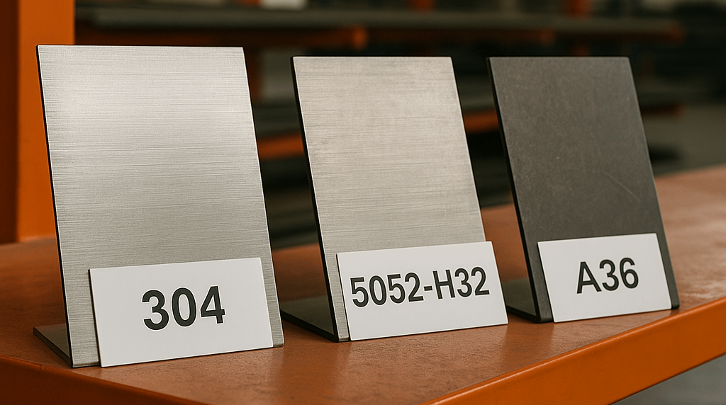
Decision Point #1: Material Selection - Beyond the Spec Sheet
Choosing a material is far more than matching a callout on a spec sheet; it is the first and most fundamental balancing act in our framework. The choice directly dictates the baseline for performance and cost, while heavily influencing manufacturability.
When evaluating how to choose material for sheet metal, your decision should be a strategic one, informed by the end-use application and total project budget.
Calibrating for Performance vs. Cost:
Mild Carbon Steel (A36, 1018): Cost baseline; easy to cut/weld/bend. Press brake note: typical V‑die opening ≈ 6–10×T works well; coatings (powder/zinc) handle corrosion. Use for: general brackets, high‑volume parts with secondary finishing.
Stainless (304, 316): High corrosion resistance; higher forming force and springback; greater tool wear. 304 suits indoor/standard environments; 316 for chlorides/marine. Process note: expect larger over‑bend and tighter QC of angles.
Aluminum (5052, 6061): Lightweight, naturally corrosion‑resistant. 5052‑H32 is the default for aluminum U‑channel bending; 6061‑T6 needs larger R or form in softer temper then heat‑treat. Design note: plan R and grain orientation early.
Decision Point #2: Bend Radius Rules for Sheet Metal U-Channels
Nothing impacts strength and yield more than bend radius.
Rule of thumb:R ≥ T (increase for SS & 6061). Too tight → thinning, micro‑cracks, poor cosmetics.
Tooling alignment: Use your fabricator’s standard punch radii to avoid custom tooling cost/lead‑time.
Quick picks — recommended inside R (typical shop baselines):
Thickness (T)
5052‑H32
6061‑T6
304 SS
1.0 mm
≥ 1.0 mm
≥ 1.5–2.0 mm
≥ 1.5 mm
1.5 mm
≥ 1.5 mm
≥ 2.0–2.5 mm
≥ 2.0 mm
2.0 mm
≥ 2.0 mm
≥ 3.0 mm
≥ 2.5–3.0 mm
Baseline only; confirm with your supplier’s tooling library.
Worked example: switching a 2.0 mm 6061‑T6 inside radius from 1.0T → 1.5T typically reduces edge cracking risk and rework, and often improves surface grade to pass cosmetic criteria—without tooling changes.
Standard vs custom tooling — when do you trigger custom?
Required inside R has no matching punch in the library
Deep U beyond press brake throat depth / V‑opening
Extremely narrow flanges that need special fingers → Expect tool cost + additional tryouts + longer lead time.
Decision Point #3: Minimum Hole Distance from a Sheet Metal Bend
Keep features ≥ 2T + R from the bend tangent to avoid distortion and stress risers. Teardropping and misalignment are common root causes of assembly scrap.
If space is tight, consider:
Re‑orient the blank so bends go across grain, gaining formability margin.
Operation re‑sequence: pre‑pierce pilot holes, form, then finish‑size with a secondary op.
Add corner/slot reliefs to control material flow at the bend.
Clear feature placement is a DFM win: predictable results, lower scrap, smoother assembly.
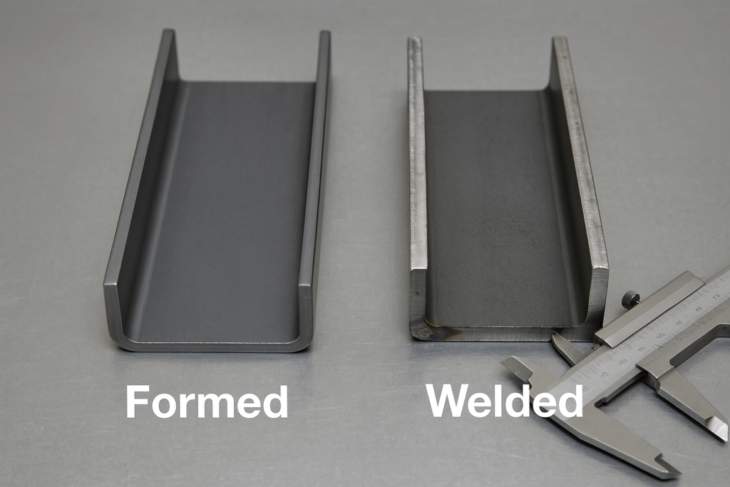
Part 3: The Critical Juncture — Formed vs. Welded U-Channel Decision Matrix
The Most Important Cost Decision You Will Make
This choice appears when channel depth/flange length exceed press‑brake limits. It impacts labor, tooling, lead time, and fatigue behavior.
Cost crossover example (illustrative):
Formed: setup amortized by volume; cycle ≈ seconds; minimal post‑process
Welded: cut + fit + weld + grind; labor‑minutes per part → At ≤ 60–80 pcs per build, welding may be comparable; beyond that, forming typically wins on unit cost and takt time (shop‑dependent). Decide with your supplier’s real rates.
Prefer forming for high-load / vibration applications
Manufacturing Cost (Per Unit)
Lower — fewer steps, faster cycles
Higher — cutting, fitting, welding, finishing
Forming dominates at medium–high volumes
Lead Time
Shorter; streamlined process
Longer; multi-step workflow
Form when deadlines are tight
Design Flexibility
Limited by press brake depth & tooling
Very high; extreme depths and mixed gauges
Weld only when geometry demands it
Aesthetic Consistency
Clean and seamless
Weld seams/distortion risk
Forming for visible/cosmetic parts
The conclusion from this matrix is clear and actionable for any procurement professional or engineer. If your design can be modified to accommodate the limitations of press brake forming without compromising its core function, it is almost always the superior strategic choice for optimizing ROI and mitigating production risk.
It delivers a stronger, cheaper, and more consistent part, faster. A welded assembly should be reserved for situations where the design’s geometric requirements are absolute and cannot be achieved through forming. This single decision, made early in the process, can have a greater impact on the final cost and timeline than almost any other design parameter.
By internalizing these DFM practices, you move from part design to manufacturing architecture—saving weeks of churn and rework.
Case Study: Preventing Cracks in an Aluminum U-Channel
Original design Material: 6061-T6 aluminum Thickness: 2 mm Inside bend radius: 1 mm
Problem During press brake bending, small cracks appeared along the outer bend surface.
Root cause
• Bend radius too small for 6061-T6 • Bend direction parallel to rolling grain
Solution
• Increase inside bend radius to 3 mm • Rotate the blank so bending occurs across the grain direction
Result
The crack rate dropped from about 15% during prototype testing to less than 1% in production.
Part 5: Real-World Problem Solving - An Interactive Troubleshooting Guide
Theory and guidelines are essential, but the real test of knowledge—and a supplier’s experience—comes when confronting real-world problems. Here are some common scenarios encountered during prototyping and production, along with expert analysis on their root causes and solutions.
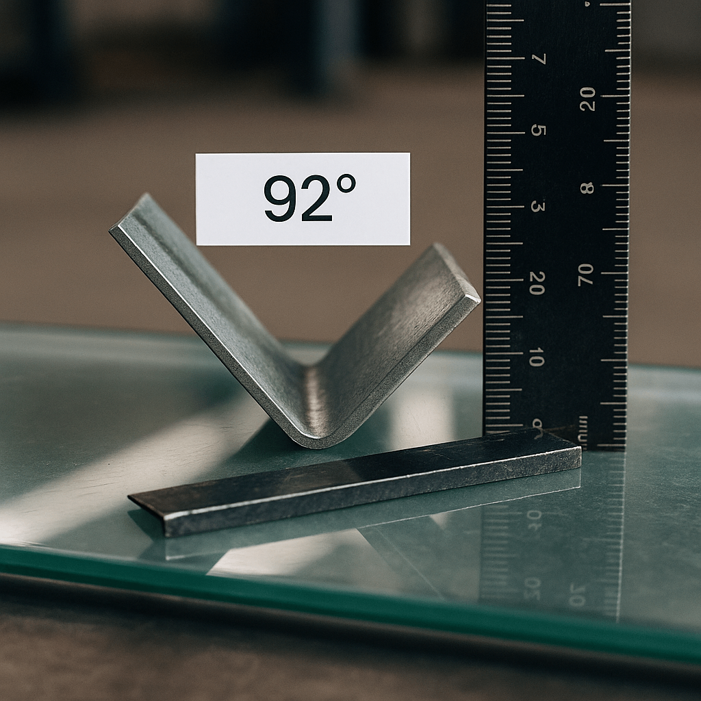
Scenario 1: "My prototype part came back, and the flanges aren't 90 degrees. Why?"
This is classic springback. A 90° punch may yield 92° on release; pro shops over‑bend to land on print.
Cause: Material, thickness, and radius drive elastic recovery (SS > MS > 5052).
Solution:Springback compensation with calibrated over‑bend; verify per batch.
Verification action: Record programmed angle vs. measured result for first‑article parts; log material heat/lot for traceability.
Scenario 2: "I see small cracks near the bend on my aluminum part. What are the likely culprits?"
Too‑tight radius (R < recommended)
Bending with the grain (parallel orientation)
Alloy/temper choice (6061‑T6 formed too late)
Fixes: Increase R; rotate layout to bend across grain; form in softer temper then age.
Verification action: Make coupon bend tests (across/with grain) and microscope edge checks before full run.
Scenario 3: "How do I communicate a critical tolerance on just one dimension of my U‑channel?"
Issue: Global title‑block tolerances may be too loose for one feature.
Solution: Add local tolerance next to the critical dim (e.g., 50.00 ± 0.10 mm) and a flag note (CRITICAL FOR ASSEMBLY). Consider a go/no‑go gauge or CMM reference.
Verification action: Define a CTQ inspection step and sampling plan on the PO or print.
Frequently Asked Questions (FAQ)
Q1: What materials are best for sheet metal U-channel fabrication? A: Mild steel for cost efficiency, 304/316 for corrosion, 5052/6061 for weight. For aluminum U‑channel bending, 5052‑H32 is most formable. (See Part 2.)
Q2: How do I ensure my design fits standard press brake tooling for U channels? A: Align inside R with standard punches; share STEP + PDF in RFQ for DFM review. (See Part 2: Bend Radius.)
Q3: What tolerances are typical for sheet metal U-channel parts? A: Use ISO 2768‑m globally; apply local ±0.10 mm on assembly‑critical features. (See Part 4.)
Q4: What is the minimum hole distance from a sheet metal bend? A: Respect 2T + R from feature edge to bend tangent; add reliefs or re‑sequence if tight. (See Part 2: Feature Placement.)
Q5: Formed or welded—how do I choose? A: Form when geometry allows (stronger/faster/cheaper in volume); weld for extreme depths or mixed gauges. (See Part 3.)
Q6: Typical lead times for prototypes and production? A: Prototypes in 5–7 working days for standard materials; production varies with volume and finishing.
Q7: What QA documentation can you provide? A: Material certs (mill test), COC, dimensional inspection reports (FAI), and PPAP‑style packages on request.
Q8: Do you support gauges/fixtures for critical U‑channel dimensions? A: Yes—simple go/no‑go gauges for flange width/height or custom fixtures for parallelism reduce inspection time and scrap.
Conclusion: From Designer to Decision‑Maker
A “simple” U‑channel succeeds when trade‑offs are explicit, not accidental. Use the triangle to set priorities, then tune material, radius, features, and forming method to match.
Go‑live checklist (keep this with your RFQ):
Unify inside R and match standard punches
Keep features ≥ 2T + R or add reliefs/re‑sequence
Specify material grade + temper + thickness
Set ISO 2768‑m globally; flag local critical dims (±0.10 mm)
Attach STEP + PDF, finish spec with masking map, and EAU
Before sending drawings to a fabricator, review the following checklist to avoid common U-channel design problems.
U-Channel Design Checklist
• Inside bend radius ≥ material thickness • Holes placed at least 2T + R from bends • Material grade and temper clearly specified • Grain direction considered for aluminum parts • Critical dimensions clearly tolerance-controlled
Following these guidelines can significantly improve manufacturing consistency and reduce production risk for sheet metal U-channel parts. Last updated: March 2026
If you have any questions or need a quote, please send us a message. One of our specialists will get back to you within 24 hours and help you select the correct valve for your needs.