
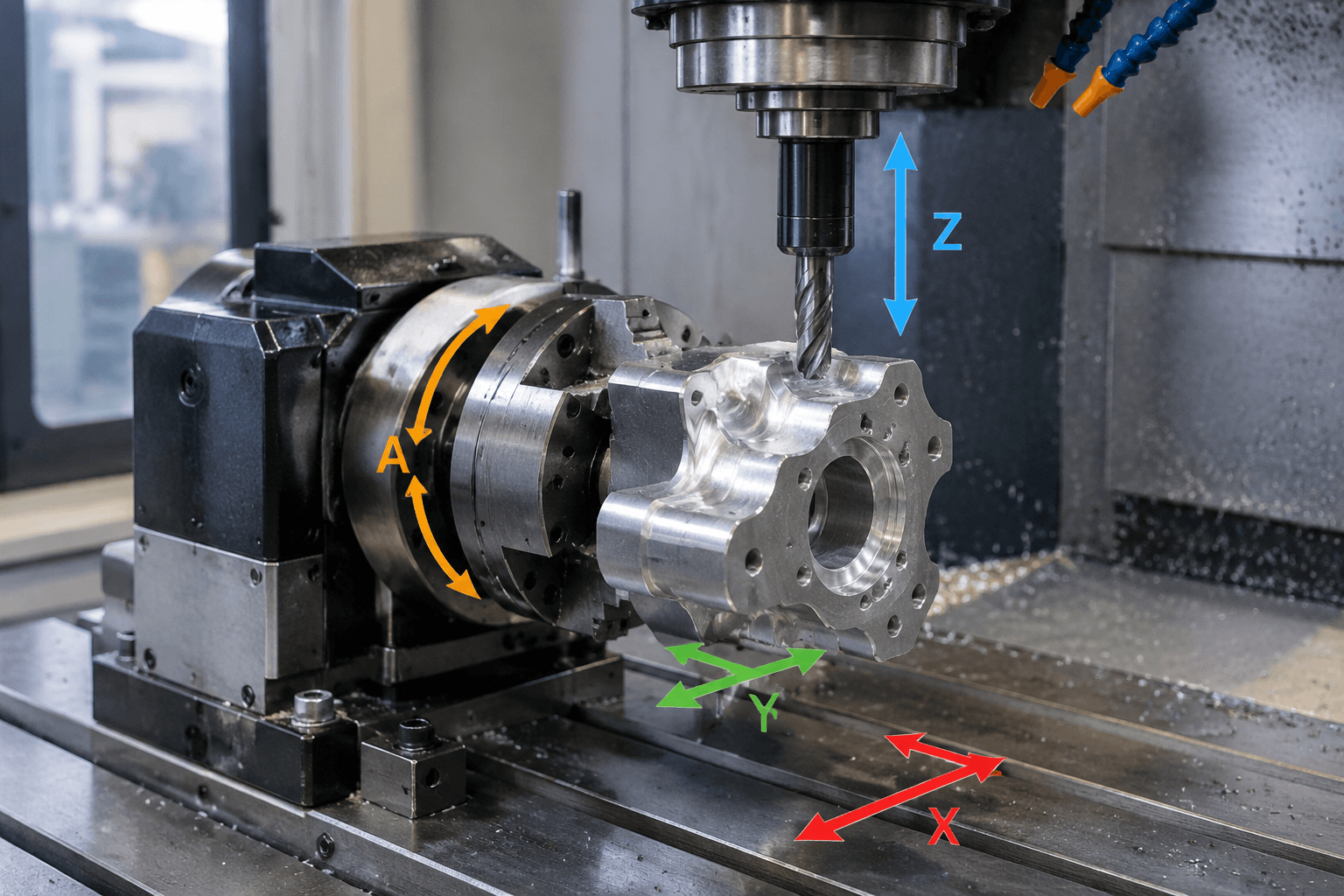
4-axis milling combines movement along the X, Y, and Z linear axes with controlled rotation around an additional axis, commonly called the A axis. Its practical value depends on how features are distributed around the workpiece, whether the cutter can reach them, and whether the part can be held securely without fixture interference.
The fourth axis does more than add another direction of motion. It changes how engineers plan part orientation, establish the rotary centerline, select workholding, create toolpaths, and inspect relationships between features. Some parts only need indexed repositioning between operations. Others benefit from cutting while the workpiece rotates continuously.
The following process explanation shows how those two modes work, where 4-axis milling can reduce repositioning, and what information a manufacturer needs before deciding whether it is suitable.
X = left-to-right linear movement
Y = front-to-back linear movement
Z = vertical tool movement
A = controlled rotation around the X-axis
The exact rotary-axis designation depends on the machine configuration. Rotation around the Y-axis is normally designated B, while rotation around the Z-axis is designated C.
How the Rotary Axis Changes Tool Access
In a conventional 3-axis milling operation, the cutter and workpiece move relative to each other along three perpendicular linear axes. The part remains in a fixed angular orientation during each cutting cycle. Reaching another face may require the operator to stop the process, reposition the workpiece, establish the new orientation, and verify the setup again.
A 4-axis configuration adds controlled rotation. The workpiece is typically mounted to a rotary table, chuck, collet fixture, or purpose-built fixture connected to the rotary axis. The control system can then position the component at a commanded angle or coordinate rotary movement with linear-axis movement.
There are two important operating patterns:
- Indexed 4-axis milling: The rotary axis turns the part to a specified angular position and then holds it stationary while the X, Y, and Z axes perform the cut. This is sometimes described as 3+1 machining because three axes cut after one rotary axis positions the workpiece.
- Continuous 4-axis milling: The rotary axis moves during cutting, coordinated with one or more linear axes. This permits toolpaths that follow a curved or circumferential surface, provided the cutter, holder, fixture, and machine structure have sufficient clearance.
These modes should not be treated as interchangeable. Indexed machining divides the program into defined orientations and is often easier to visualize. Continuous motion requires a suitable toolpath strategy, controlled rotary feed, and careful collision review. It is not automatically necessary simply because a machine has four controlled axes.
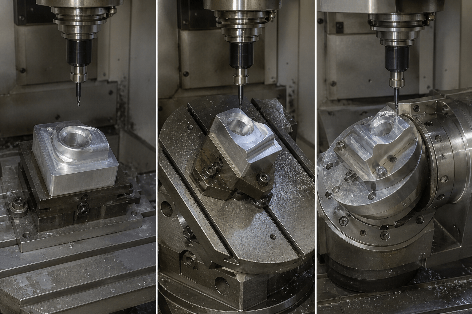
- Fixed 3-axis setup: Machine the accessible top features, stop, refixture the part, and continue on another face.
- Indexed 4-axis setup: Rotate the mounted part to a new angle, lock the position, and machine the newly presented face.
- Continuous rotary toolpath: Coordinate rotation with linear movement to cut a profile around part of the circumference.
From CAD Geometry to a Rotary Milling Setup
Adding a rotary axis changes planning well before metal is cut. The CAD model must first be interpreted as a set of machinable features rather than simply as a finished shape. Feature direction, tool approach, datum relationships, stock geometry, and fixture contact all affect whether a rotary setup is practical.
- Review feature distribution. The programmer identifies holes, slots, pockets, flats, profiles, and other features located around the component. Features sharing a common rotary centerline may be good candidates for indexed or continuous 4-axis operations.
- Define the rotation axis. The intended rotary centerline is established relative to the model and the physical setup. If this relationship is misunderstood, features may be programmed at the wrong angular position or at an incorrect distance from the centerline.
- Select a stable holding method. The setup must resist cutting forces while preserving access. A long part may need tailstock or support-fixture consideration, while an irregular body may require a custom fixture. Support can improve stability but may also block a tool approach.
- Orient the workpiece. The chosen orientation determines which surfaces face the cutter during rotation. It must also leave room for clamps, jaws, fasteners, the cutter body, and the toolholder.
- Choose indexed or continuous motion. Separate planar features at known angles may suit indexing. A profile extending around a cylindrical or curved surface may require coordinated rotary cutting. A component can use both approaches in the same overall process.
- Build and simulate toolpaths. CAM programming defines tool orientation, cutting direction, rotary movement, entry and exit motion, and linking moves. Simulation should evaluate more than the cutter tip; the holder, fixture, stock, supports, and rotary hardware can also create collision risks.
- Plan verification. The drawing determines which dimensions, angular relationships, datums, and surfaces need inspection. Inspection verifies the specified result; it is not an extra machining axis and does not compensate for incomplete manufacturing requirements.
This workflow explains why tool access cannot be judged from the final CAD shape alone. A feature may be visible on screen but unreachable with the selected cutter because the holder contacts a shoulder, the fixture blocks the approach, or another section of the part prevents the required orientation.
Feature Arrangements That Can Benefit from Rotary Access
4-axis milling is most relevant when useful machining directions are distributed around a common axis. Consider a hypothetical rectangular component with holes on four side faces. A 3-axis process might machine one face, followed by several separate setups. An indexed fourth axis could present each side to the cutter without removing the component from its primary fixture.
Other potentially suitable arrangements include:
- Radial holes positioned at defined angles around a body
- Flats, keyways, or slots distributed around a shaft-like component
- Repeated pockets located around a circular or polygonal form
- Profiles that wrap around part of a cylindrical surface
- Features whose angular relationship is important to the drawing definition
- Several machinable faces that can be presented by rotating around one centerline
Suitability still depends on the complete geometry. A deep pocket may require a long tool even when the rotary axis points it toward the spindle. An overhanging feature may hide another surface during rotation. Clamps can occupy the same space needed by the cutter, while a tailstock can prevent end access. Tool length, holder diameter, flute reach, stock condition, and cutting forces therefore remain part of the decision.
The fourth axis also does not guarantee complete one-setup machining. The face attached to a chuck or fixture may remain inaccessible. End features may require another orientation, and features pointing outside the available approach direction may need a different setup or process. Complex multi-angle surfaces can exceed what one rotary axis and three linear axes can reach without interference.
How 3-Axis, 4-Axis, and 5-Axis Milling Differ
The useful comparison is not which process is universally better. It is which motion arrangement provides the required access while supporting stable workholding, controllable toolpaths, and the specified feature relationships.
| Process | Available motion | Typical access pattern | Setup implications | Planning considerations |
|---|---|---|---|---|
| 3-axis milling | Three linear axes | Features reachable from a fixed orientation | Additional faces may require manual repositioning or separate fixtures | Often direct to program, but setup count depends on feature direction |
| 4-axis milling | Three linear axes plus one rotary axis | Features distributed around one defined centerline | Can present multiple angular positions without removing the part, although additional setups may still be needed | Requires rotary-centerline control, fixture clearance, angular planning, and suitable indexed or continuous toolpaths |
| 5-axis milling | Three linear axes plus two rotary axes | Surfaces requiring changes in tool or workpiece orientation across multiple angular directions | May provide access to geometry that one rotary axis cannot present | Introduces additional programming, simulation, collision-control, and setup considerations |
A part with top-facing pockets may need only 3-axis milling. Add radial holes around one centerline, and 4-axis indexing may become relevant. Add surfaces that require the cutter to approach from changing compound angles, and 5-axis access may need evaluation.
However, axis count alone does not determine process suitability, dimensional results, cycle time, or cost. The final choice depends on part size, stock form, material, geometry, tolerance relationships, surface requirements, tool access, workholding, quantity, and inspection expectations. Readers seeking a broader overview can review Yishang’s custom CNC machining information.
Does This Part Actually Need 4-Axis Milling?
Use this compact process-fit matrix as a starting point, not as a substitute for reviewing the complete model and drawing.
| Part condition | Likely process implication | Question to resolve |
|---|---|---|
| All important features face one primary direction | 3-axis milling may be sufficient | Can every feature be reached with practical tools from a fixed setup? |
| Planar features appear on several sides around one centerline | Indexed 4-axis milling may reduce manual repositioning | Can the fixture expose each face without blocking the cutter? |
| A profile follows a circumference or curved path | Continuous rotary motion may be useful | Can the CAM strategy coordinate rotation while maintaining clearance? |
| Features require compound-angle approaches | A single rotary axis may be insufficient | Would another setup work, or is 5-axis access necessary? |
| The mounting face also contains critical features | An additional setup may remain necessary | How will the part be relocated while preserving datum relationships? |
| A long or slender part needs extra support | Stability and access must be balanced | Will the support method interfere with tools or end features? |
If the immediate objective is only to evaluate fit, handling, or assembly space before committing to machined production, a physical prototype made by another method may sometimes answer the first design question. Yishang’s information on 3D printing for fit and assembly validation provides one possible route for that earlier stage.
Information Needed for a Reliable Process Review
A 3D model communicates shape, but it may not define manufacturing intent completely. For a meaningful 4-axis milling review, provide the following information:
- Native or neutral 3D CAD model
- The model supports geometry review, feature recognition, orientation planning, and interference assessment. It should represent the intended revision of the part.
- Controlled 2D drawing
- The drawing should identify dimensions, tolerances, datums, geometric controls, threads, edge conditions, and other requirements that cannot safely be inferred from nominal geometry.
- Critical feature relationships
- Mark the holes, surfaces, angular positions, or interfaces that affect assembly or function. This helps determine whether features should remain in one setup or can be divided across setups.
- Material and starting-stock requirements
- Material condition and stock form can influence holding strategy, cutter selection, deformation risk, and process sequence.
- Finish requirements
- Identify coatings, plating, conversion treatments, cosmetic expectations, and any surfaces that must remain free of fixture marks. Machining finish and post-machining treatment should be specified separately where appropriate.
- Quantity and repeat requirements
- Prototype and repeat-production quantities can justify different fixture strategies. State whether future batches must follow the same revision and inspection requirements.
- Inspection expectations
- Define critical characteristics, required records, sampling expectations, and any special measurement conditions. Requirements should come from the drawing or purchasing specification rather than assumptions.
For an informed process review, send Yishang the 3D CAD model, a 2D drawing with critical tolerances and datums, material and finish requirements, required quantity, and inspection expectations. Yishang supports B2B OEM and ODM custom manufacturing; the purpose at this stage is to review process fit from complete part information before preparing a quotation.
Frequently Asked Questions
What is the main difference between 4-axis and 5-axis milling?
4-axis milling adds one rotary axis to three linear axes, so the part or tool can be oriented around one rotational direction. A 5-axis process adds a second rotary direction, allowing access from a wider range of compound angles. The need for five axes depends on geometry, tool approach, fixture clearance, tolerances, and setup strategy—not simply on part complexity.
Does 4-axis milling always machine continuously while the part rotates?
No. In indexed 4-axis milling, the part rotates to a commanded angle and remains stationary while cutting occurs. In continuous 4-axis milling, rotary and linear movement are coordinated during the cut. A process may use indexed movement, continuous movement, or both.
Can a 4-axis mill machine every side of a part in one setup?
Not necessarily. The mounting face may be blocked by the fixture, end features may be inaccessible, and some surfaces may require an approach that one rotary axis cannot provide. Toolholder clearance, clamps, supports, and surrounding geometry must all be checked before claiming one-setup access.
What files and specifications help determine whether a part suits 4-axis milling?
Provide a current 3D CAD model and a controlled 2D drawing showing dimensions, critical tolerances, datums, geometric controls, threads, and finish requirements. Material, stock condition, quantity, critical feature relationships, and inspection expectations are also needed to evaluate tool access, workholding, setup count, and verification requirements.