
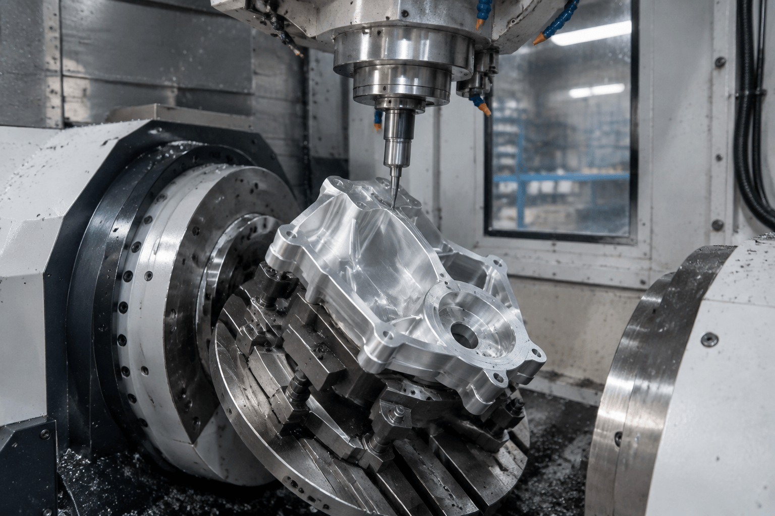
A 5 axis CNC service is most relevant when a part’s geometry, tool access, setup strategy, or tolerance requirements make multi-directional machining valuable. The axis count alone does not establish supplier fit: the machine configuration, programming method, workholding, material experience, inspection plan, and interpretation of the drawing all affect whether the process is appropriate.
In short: 5-axis machining uses three linear axes and two rotary axes to position or move the cutting tool around a component. It can be useful for angled features, deep cavities, undercuts, and parts that are difficult to reach accurately with repeated 3-axis setups, but a 3-axis or 4-axis process may remain the better choice when the geometry and datum strategy are straightforward.
What a 5 Axis CNC Service Delivers for Complex Milled Parts
In a conventional 3-axis milling process, the tool moves along X, Y, and Z. The workpiece may need to be repositioned or re-clamped to reach additional faces. A 5-axis machine adds two rotary axes, often identified as A, B, or C depending on the machine configuration. These rotary movements change the angle between the cutting tool and the workpiece.
That additional movement does not automatically make every part a 5-axis job. It becomes valuable when the design contains several faces that must be machined in relation to one another, angled passages, deep pockets, compound surfaces, or undercut regions. Tilting the tool can improve access and allow a shorter, more suitable cutter to reach a feature. In other cases, the main benefit is reducing the number of times the part must be removed and re-established in a fixture.
Two decision-level categories are important:
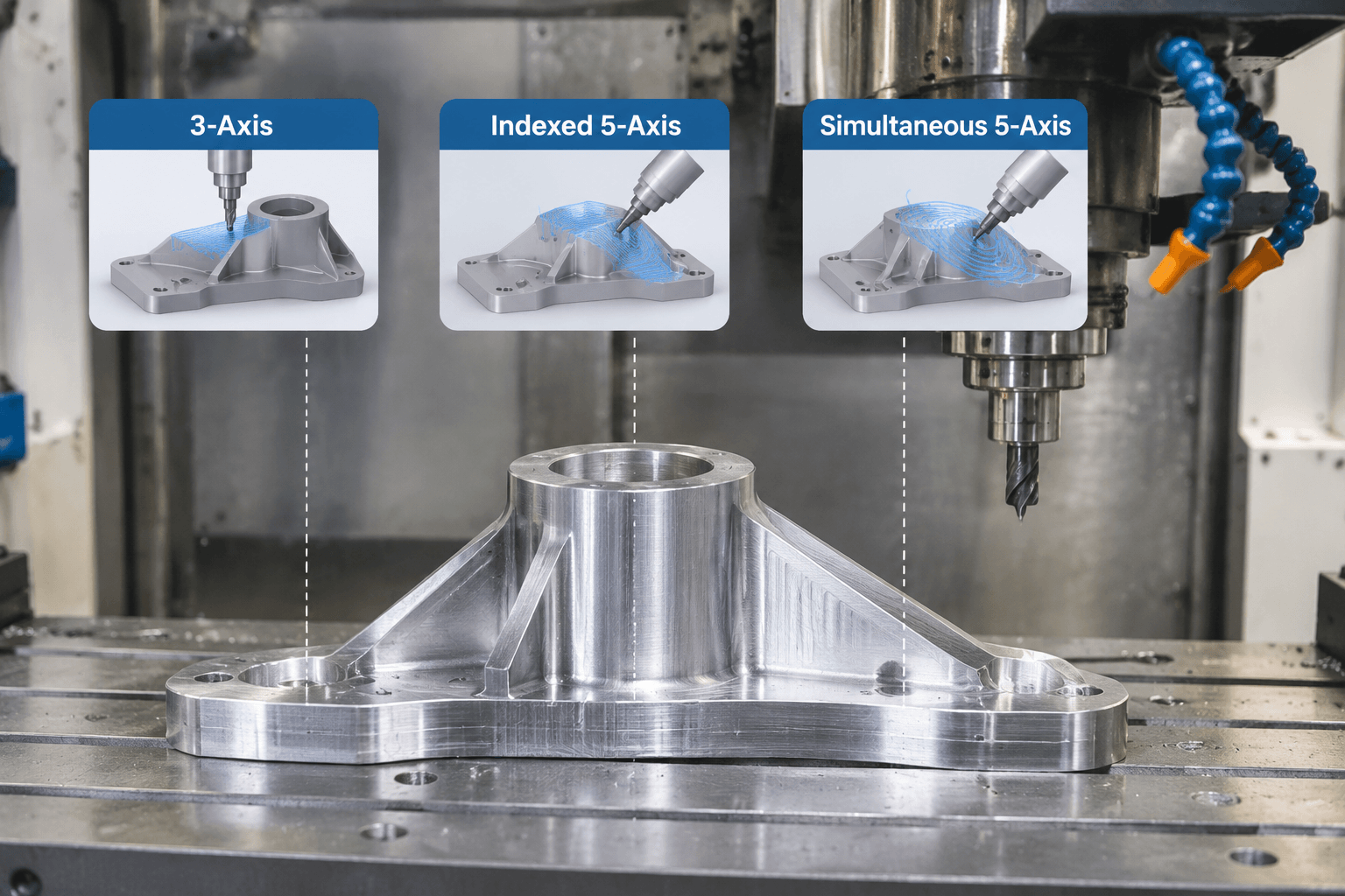
- Indexed, or positional, 5-axis machining: the rotary axes move the workpiece or tool into a new orientation, then remain fixed while cutting takes place. The process may still use conventional 3-axis toolpaths for each orientation.
- Simultaneous 5-axis machining: the linear and rotary axes move together during cutting. This can support continuously changing tool orientation on complex surfaces, but it requires appropriate CAM programming, post-processing, collision checking, tooling, and machine control.
A supplier should therefore explain which type of 5-axis work is intended for your part. A statement that a shop has “5-axis capability” is less useful than a review of the actual CAD model, feature access, tool orientation, fixture concept, and critical datums.
Choosing Between 3-Axis, 4-Axis, and 5-Axis Milling
The right process is determined by the part rather than by the highest available axis count. A simple prismatic component with accessible top and side features may be efficiently produced with 3-axis milling and carefully planned setups. A rotary-indexed feature pattern may suit 4-axis machining. A part with multiple angled faces or continuously changing surfaces may justify indexed or simultaneous 5-axis work.
| Decision factor | 3-axis milling | 4-axis milling | 5-axis milling |
|---|---|---|---|
| Feature access | Best for accessible faces and straightforward pockets | Useful when rotary positioning adds access around one primary rotation | Useful when several orientations or changing tool angles are needed |
| Setups | May require more repositioning for multi-face parts | Can reduce repositioning for suitable cylindrical or indexed features | May reduce setups when the fixture and datum strategy support it |
| Tool orientation | Usually fixed relative to the workpiece during a toolpath | Rotary positioning adds another orientation option | Can use indexed or continuously changing tool orientation |
| Typical design question | Can every critical feature be reached accurately from planned setups? | Does one rotary direction solve the access problem? | Do several angled or compound features require coordinated movement? |
This is not a universal ranking. Material, part size, quantity, tolerances, surface-finish requirements, and programming time can change the practical decision. A more complex machine may not reduce total cost if the part is simple, the quantity is small, or the required toolpaths are difficult to validate. Conversely, repeated setups on a complex component may introduce datum-transfer risks that make multi-axis access attractive.
Ask the supplier to compare at least two plausible process routes. The comparison should identify the proposed setups, primary datums, accessible features, expected tooling approach, and inspection sequence. For a critical part, the question is not simply “Can this be cut on 5 axes?” but “Which process best controls the relationship between the features that matter?”
What to Verify Beyond the Machine’s Axis Count
Supplier evaluation should focus on evidence connected to your component. Start with the machine configuration and usable work envelope. The nominal number of axes does not tell you whether the table, spindle arrangement, rotary travel, fixture height, or access around the actual part is suitable. Ask how the component would be oriented and whether the proposed setup leaves room for the tool, holder, probes, and workholding.
CAD/CAM practice is equally important. For indexed work, the supplier should be able to define reliable orientations, datum relationships, and toolpaths for each face. For simultaneous work, ask how the team manages post-processing, tool-axis transitions, collision avoidance, gouge checking, and verification of the output code. These controls are especially relevant where the design includes deep cavities, thin walls, blended surfaces, or changing tool angles.
Workholding deserves a specific discussion. A fixture must hold the part securely without blocking critical surfaces or distorting thin sections. It may also need repeatable locating features so that a second operation references the intended datum rather than an uncertain transferred position. A supplier’s proposed fixture concept can reveal more about feasibility than a generic list of machine capabilities.
Tooling decisions should address cutter reach, rigidity, corner access, material behavior, and the relationship between tool length and surface quality. Do not assume that a 5-axis toolpath eliminates all cutting constraints. Long tools can deflect, tight internal corners may require a different strategy, and the best surface result may require separate roughing, semi-finishing, and finishing operations.
Finally, clarify how the supplier will inspect the part. Critical dimensions need defined datums, measurement methods, and acceptance criteria. Ask whether inspection will be based on the drawing, the 3D model, a customer-supplied report format, or another agreed method. A capable machining process can still produce an unsuitable result if the supplier and buyer interpret profile, position, flatness, or orientation requirements differently.
For broader context on production workflow, see Custom CNC Machining From First Sample to Repeat Production. It is also useful to separate machining capability from prototype validation: a 3D printing prototype may help identify fit and assembly issues before committing to a machined version, but it does not prove that the final material, finish, or machined datum strategy is acceptable.
Prepare an Engineering-Ready 5-Axis Machining Inquiry
A supplier can judge feasibility more accurately when the inquiry describes the part’s functional requirements, not only its desired process. Prepare the following information before requesting a quotation:
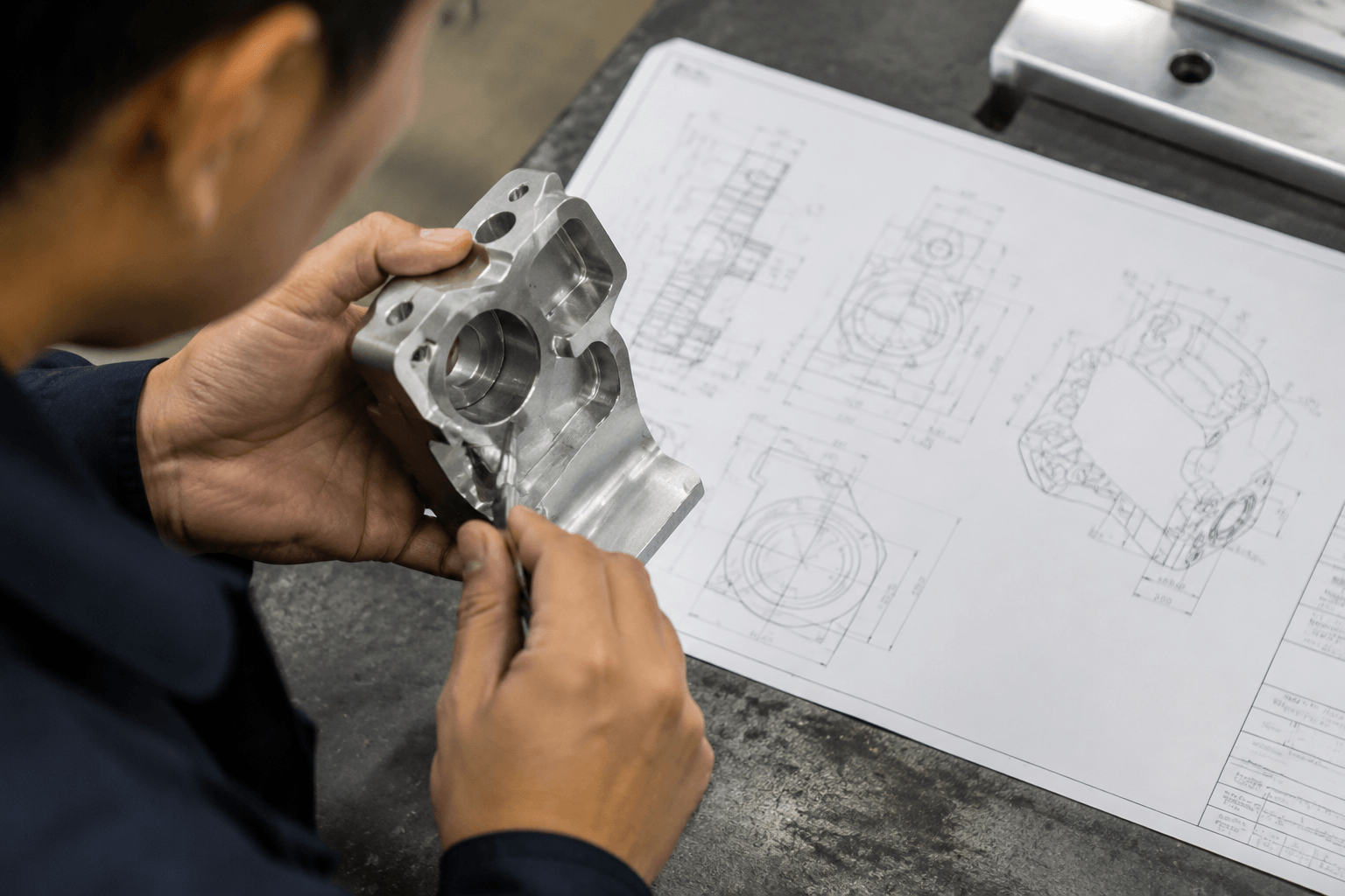
- Send the 3D CAD model and available drawings. The model communicates overall geometry, while the 2D drawing commonly defines datums, dimensions, tolerances, notes, and inspection requirements that may not be clear from the model alone.
- Identify the material and condition. State the alloy or engineering material, condition where relevant, and any requirements affecting cutting behavior or downstream treatment. If the material is not finalized, say so rather than allowing suppliers to quote against different assumptions.
- Mark critical features and tolerances. Identify interfaces, hole patterns, bearing or sealing locations, wall thicknesses, positional relationships, and any dimensions that control assembly or function. General dimensions and critical dimensions should not be treated as equivalent.
- Define surface requirements. Include surface-finish expectations, cosmetic areas, edge conditions, deburring requirements, and any regions that must remain masked during a later treatment. A finish applied after machining may change the final condition of a surface.
- State quantity and production context. Include prototype, sample, pilot, repeat, or production intent where known. Quantity influences fixture economics, process validation, tooling decisions, and how much programming preparation is practical.
- Explain inspection expectations. Specify required reports, sampling expectations, customer witness requirements, or special measurement needs. If there is no fixed format, ask the supplier to propose an inspection plan for approval.
- List downstream requirements. Mention anodizing, plating, painting, heat treatment, assembly interfaces, inserts, welding, or packaging constraints separately from the machining operation. This helps the supplier protect datums and surfaces through the complete manufacturing route.
- Provide delivery and commercial context. Include the target delivery window, destination, packaging needs, and any documentation requirements. These details do not replace technical information, but they help prevent quotations based on incompatible assumptions.
Missing information can make supplier comparisons unreliable. One quotation may assume a simple indexed process, another may include additional inspection, and a third may price a different material or finishing route. Requesting the supplier’s assumptions in writing makes the proposals easier to compare.
Keep Machining, Finishing, Inspection, and Assembly Distinct
CNC machining removes material to create the specified geometry. Finishing is a downstream treatment or surface operation that may change appearance, corrosion behavior, hardness, or surface condition; it is not a replacement for controlling the machined feature itself. Inspection verifies conformity against agreed requirements, while assembly joins machined or fabricated components into a larger product.
These stages interact. A machined datum may need protection during anodizing or painting. A hole used for assembly may require inspection before a coating is applied. A fixture may need to expose a surface that will later mate with another component.
The same distinction applies to other manufacturing processes. CNC turning is generally suited to primarily rotational parts, although turned parts may interface with a milled or fabricated assembly. Sheet metal fabrication addresses cut, formed, or bent components. Welding and assembly join parts; they do not become interchangeable with milling simply because they appear in the same product.
For OEM and ODM projects involving a wider product context, Yishang reports more than 26 years of experience manufacturing custom sheet metal parts and metal products, exporting to more than 50 countries, and supporting B2B custom manufacturing projects. The company also states that it holds ISO and RoHS certifications. Those facts do not by themselves confirm a particular 5-axis machining route, so the part-specific feasibility review remains essential.
For a qualified review, submit the 3D CAD model and drawing together with the material, quantity, critical tolerances, surface-finish requirements, inspection expectations, and any finishing, assembly, or delivery constraints. This allows Yishang to first confirm whether it can support the requested machining route and, if so, assess process fit before preparing a scoped proposal.
Frequently Asked Questions
What is 5-axis milling, and how is it different from standard 3-axis milling?
5-axis milling combines X, Y, and Z linear movement with two rotary axes. This allows the tool or workpiece to be positioned from additional directions and, in simultaneous machining, to change orientation while cutting. Standard 3-axis milling can still be suitable when all important features are accessible through straightforward setups.
What is the difference between indexed and simultaneous 5-axis machining?
Indexed 5-axis machining uses the rotary axes to place the part or tool in a fixed orientation before a conventional cutting operation. Simultaneous 5-axis machining coordinates linear and rotary movements during cutting, which can support complex surfaces and changing tool angles. The suitable method depends on the geometry, CAM strategy, tooling, and verification requirements.
When is 5-axis machining unnecessary for a part that can be made with 3-axis or 4-axis milling?
It may be unnecessary when the part has accessible faces, simple feature relationships, manageable setups, and no need for continuously changing tool orientation. A simpler process can be practical when it meets the tolerance, surface, quantity, and inspection requirements without creating excessive datum-transfer risk.
Does a more complex part automatically require a 7-axis CNC service?
No. Part complexity alone does not determine the required axis count. Many components can be produced with 3-axis, 4-axis, or 5-axis milling depending on access, workholding, and feature relationships. A 7-axis process may be relevant to specialized geometries or combined operations, but it should be considered only after the actual part and manufacturing sequence have been reviewed.