
An enclosure quote can look accurate while it hides the real assembly risk. The drawing may show the outer size, bend lines, PEM studs, welds, mounting holes, and powder coat color. The purchasing team receives three prices and selects the lowest acceptable supplier. The prototype then passes a basic dimensional check.
The failure appears later, when the soldered PCB enters the metal part. A connector rubs against a folded flange. A solder joint sits too close to a bracket edge. A coated grounding stud needs scraping before the lug will seat. The enclosure matches its drawing, but the full product does not fit.
This problem starts when the RFQ treats solder material as an electronics detail and sheet metal fabrication as a separate purchase. In the finished product, both occupy the same space. Solder joint height, connector position, rework temperature, flux residue, grounding contact, and wire exit angle can all change the clearance needed around enclosures, brackets, cabinets, or welded frames.
The dominant buyer risk is not choosing the wrong alloy in isolation. The larger risk is awarding a fabrication quote before suppliers understand how the soldered assembly will live inside the metal part. When the RFQ leaves that context open, each supplier prices a different assumption. One includes masking, tighter alignment, and access review. Another prices only the metal drawing. The cheaper quote may simply exclude the risk that will later stop assembly.
The lowest enclosure quote may be pricing the wrong soldered assembly
Most fit failures begin before production, inside the RFQ package. The buyer sends a clean sheet metal drawing because the PCB drawing belongs to another team. The fabricator prices cutting, bending, welding, fasteners, and finishing. No one sees the maximum height of soldered pins, the connector overhang, or the route of a soldered ground wire.
That gap changes the quote. A supplier who sees only the enclosure drawing may apply standard sheet metal tolerances and coat all surfaces. Another supplier may ask for the PCB envelope, then include larger connector relief, masked grounding areas, and post-finish inspection. Both prices may look like quotes for the same enclosure. They are not.
A compact controller enclosure example
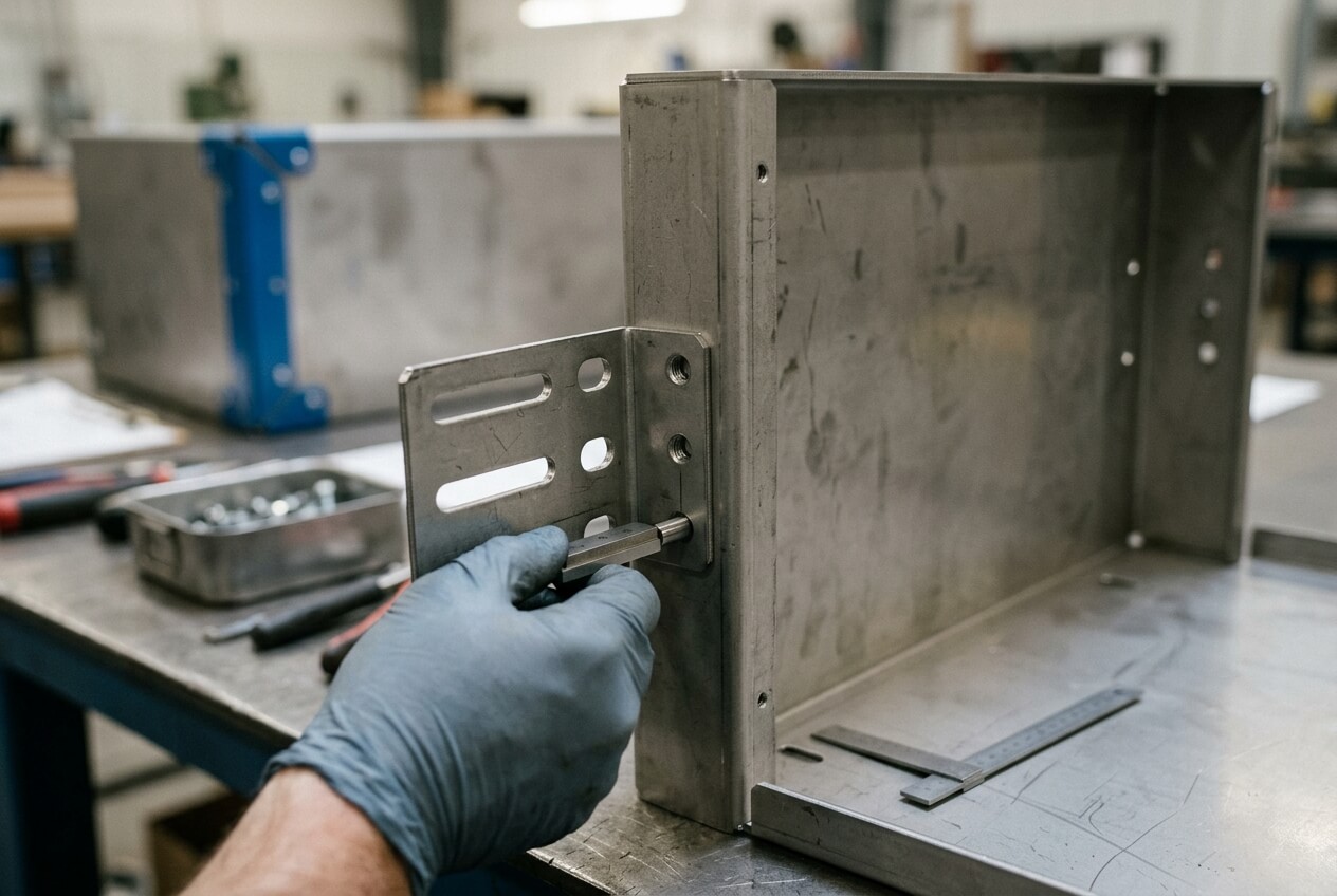
Consider a wall-mounted controller with a PCB on four pressed studs. The outer dimensions, mounting holes, front cutout, and powder coat requirement all look clear. The RFQ does not show the tallest soldered component on the underside of the board. During assembly, a solder fillet on a through-hole connector touches an internal return flange.
No single part has failed its own drawing. The flange sits within tolerance. The PCB supplier also meets its tolerance. The problem comes from a stack between two drawings that no supplier reviewed together. The buyer then faces rework, delayed shipment, and a dispute about whether the metal part or the PCB caused the issue.
A service cabinet access example
A second case involves an industrial power cabinet with soldered cable terminals near a removable service panel. The prototype passes because the door closes and the outside dimensions match the drawing. In production, technicians need room to inspect solder joints and guide wires through the cabinet. A welded cross brace blocks the soldering iron angle during rework.
The welded assembly may still meet the print. The RFQ failed to protect the service process. If the buyer had shown rework access needs earlier, suppliers could have quoted a removable bracket, revised brace position, or larger service opening. Those options cost less before fabrication than after finished cabinets sit on the assembly floor.
Where solder material assumptions turn into metal fabrication changes
Buyers often assume the sheet metal supplier does not need to know the solder alloy. In many cases, the fabricator does not need to choose it. However, solder material still affects the enclosure when heat, clearance, grounding, or compliance touches the metal design.
Sn63/Pb37 and Sn60/Pb40 tin-lead solders melt around 183°C to 190°C and flow easily. Lead-free solders such as SAC305, SAC0307, and SnCu usually require higher soldering or rework temperatures. If soldering happens outside the enclosure, the effect may stay limited. If rework happens after installation, nearby coating, labels, seals, inserts, and pressed fasteners may face extra exposure.
The alloy can also influence joint shape. Lead-free solder may form a different fillet profile than legacy tin-lead solder. A taller bead near a folded edge can reduce the working clearance. A soldered wire may exit a lug at a less predictable angle unless the drawing or work instruction controls it.
Grounding and finish assumptions create quote gaps
Grounding creates another hidden divide between quotes. A cabinet bracket with a welded grounding tab may look cheaper if the supplier powder coats every surface. A second quote may include masking around the contact pad, thread protection on the stud, and continuity-focused inspection after finishing. The second quote does not necessarily show poor competitiveness. It may include the real electrical contact requirement.
Export and compliance requirements can deepen the problem. If the product must meet RoHS expectations, leaded solder may not fit the target market. The sheet metal drawing may also need matching labels, finish notes, packaging controls, or segregation instructions. These details do not make the metal part more complex by themselves, but they affect supplier communication and the risk inside the production plan.
Clear RFQ language prevents suppliers from guessing. State whether soldering or rework happens before or after enclosure installation. Mark any soldered terminals near coated walls. Identify grounding pads that must remain conductive. Show whether flux residue can contact bare metal or whether cleaning happens before final assembly. These details help suppliers price the same risk.
Tolerance and finish stacks that hide until the PCB enters the enclosure
Assembly-fit problems often come from small variations that all remain acceptable on paper. A hole shifts slightly. A bend angle moves toward one side of tolerance. Powder coating builds on a slot edge. A soldered connector sits higher than the prototype sample. Each item passes inspection, yet the completed product binds, rubs, or loses electrical contact.
This risk rises in enclosures with PCB standoffs, front panels with soldered switches, DIN-rail brackets, cable entry plates, and welded frames that carry electronics. General sheet metal tolerances rarely protect connector alignment. They also may not control local coating thickness, stud perpendicularity, or cutout position relative to the PCB datum.
Functional datums matter more than outside dimensions
A USB port, power inlet, antenna connector, or terminal block needs alignment relative to the PCB, not only relative to the panel edge. If the connector references the board and the cutout references a different metal edge, the tolerance stack becomes unpredictable. The outside enclosure can measure correctly while the connector scrapes the cutout.
Buyers should group the features that control the soldered assembly. Studs, cutouts, mounting holes, tabs, and service openings may need one functional datum. That does not mean every dimension needs a tight tolerance. It means the dimensions that control installation need clearer control than cosmetic dimensions.
Coating can remove the last safe clearance
Powder coating thickness often looks too small to matter. A 60–100 micron coating can still reduce slot width, fill threads, weaken grounding contact, or make a PCB carrier difficult to slide into place. Internal fit surfaces may need masking, thinner coating, or inspection after finishing. Cosmetic outer panels may follow a different priority.
Finish expectations also affect cost and lead time. Masking a grounding pad, chasing a thread after coating, or inspecting connector cutouts after finish adds work. If the buyer states these requirements late, the supplier may need to requote or extend the schedule. If the RFQ includes them early, the quote reflects the real production process instead of a clean but incomplete drawing.
Yishang can review these fabrication details during drawing review when buyers provide the assembly context. The review should focus on bend lines near connector openings, stud locations, coating-free contact areas, welded brackets that block access, and inspection points after finishing. The aim is not to tighten everything. The aim is to control the few features that could stop assembly.
Why one approved prototype can still fail in the first production batch
Prototype approval can create false confidence. One sample may fit because a technician adjusted it by hand. Someone may scrape paint from a grounding point, chase a coated thread, bend a bracket slightly, or choose the easiest PCB from the sample lot. If the team does not record those fixes, production repeats the drawing rather than the working condition.
Soldered electronics add another variation stream. PCB assemblies have their own tolerances. Solder material and soldering conditions can change joint height, wetting, and component stand-off. A connector that looked centered in one sample may shift enough in production to rub a cutout. A soldered wire exit angle can also change unless the assembly instruction controls routing.
Prototype notes should become production controls
A buyer may approve a wall controller after one enclosure sample. The board slides into place, the membrane aligns, and the cable gland installs without force. In the first production batch, several covers will not close smoothly. The PCB sits high on soldered pins, the bracket bend angle runs near its limit, and coating builds on a shoulder. The clearance disappears only when all three conditions meet.
A welded display frame offers another example. The prototype uses an LED strip with neat solder joints behind a perforated panel. The next PCB batch has taller solder beads at the wire connection. A welded crossbar clears the sample but presses on the production strip. The frame drawing still looks correct. The missing requirement was the maximum solder bead envelope.
Buyers can reduce this risk by documenting what made the prototype work. Record the PCB revision, connector model, solder joint height, wire route, fastener stack, coating thickness, and measured critical clearances. Note any manual repair or adjustment. Then decide whether to add the fix to the production drawing, change the design, or relax a noncritical feature to protect cost.
Batch consistency also needs inspection that matches the failure mode. Measuring every outside dimension will not catch a connector clash. For fit-critical products, request checks for stud position relative to the functional datum, cutout location after finishing, coating thickness in slots, thread condition, and sample assembly with a PCB or mock-up.
What buyers should clarify before comparing fabrication quotes
Quote comparison becomes risky when the buyer compares prices before comparing assumptions. A low quote may use standard hole tolerances, coat all surfaces, and skip post-finish checks. A higher quote may include masking, tighter inspection, connector relief, and prototype assembly review. The purchasing decision should separate price difference from risk difference.
Start by identifying the features that affect the soldered electronics. For an enclosure, those features may include PCB standoffs, connector cutouts, gasket channels, grounding studs, cover screws, and internal flanges. For a welded frame, review bracket spacing, diagonal squareness, crossbar location, and mounting holes after welding. For a cabinet, check DIN rail position, cable entry alignment, door clearance, and access for soldered or crimped wiring.
The RFQ should show what the sheet metal drawing cannot show alone. A STEP file with the board and connectors helps. A section view can show maximum solder joint height. Photos from an older product can explain wire routing and service access. Notes can state whether soldering, cleaning, inspection, or rework happens before or after installation.
Cost drivers should appear before award, not after the first assembly problem. These may include tighter local tolerances, secondary drilling or reaming, welding sequence control, fixture design, coating masks, conductive contact areas, special packaging, or sample fit checks. Lead time also depends on these choices. A supplier can plan them if the RFQ includes the details early.
Communication with the fabricator should focus on consequence chains. Ask which assumptions affect fit, finish, grounding, and rework access. Ask which dimensions need inspection after powder coating. Ask whether a wider cutout, changed bend sequence, removable service bracket, or different grounding mask would reduce production risk. These questions help buyers compare buildable quotes, not just attractive unit prices.
For custom sheet metal fabrication projects, Yishang can review drawings, quantities, material requirements, tolerances, finish expectations, and assembly notes before quoting. Send PCB envelopes, soldered component heights, connector locations, grounding needs, prototype photos, and any batch history. This lets the quotation reflect the real enclosure, bracket, cabinet, frame, or welded assembly that must work in production.
Planning a sheet metal enclosure, bracket, cabinet, frame, or welded assembly around soldered PCBs, terminals, grounding lugs, or cable connections? Send Yishang your drawings, material requirements, order quantities, critical tolerances, finish expectations, STEP files or photos, and any soldered component envelopes. The earlier the RFQ shows assembly clearances and finish risks, the easier it becomes to quote the right part instead of the cheapest assumption.
Frequently Asked Questions
Why does solder material matter when buying sheet metal enclosures?
Solder material matters when soldered joints, connectors, wires, or grounding lugs sit close to fabricated metal. Lead-free solder may need higher rework temperatures and may create different joint profiles. Those details can affect clearance, coating protection, grounding contact, and service access inside the enclosure.
What should an RFQ show when a PCB mounts inside a metal enclosure?
The RFQ should show the PCB envelope, maximum solder joint height, connector overhang, stud locations, grounding areas, wire routing, and any rework access needs. A STEP file or section view helps suppliers quote the same assembly risk instead of guessing from the enclosure drawing alone.
How can powder coating create a soldered PCB fit problem?
Powder coating can reduce slot width, build on shoulders, fill threads, or cover grounding contact surfaces. A small coating build-up may remove the last clearance around a connector or solder joint. Buyers should mark masked areas and post-finish inspection points when coating affects assembly.
Why can a prototype fit but the first batch fail?
A prototype may fit because someone made an unrecorded adjustment, selected a favorable PCB, or scraped coating from a contact point. Batch production then exposes normal variation in solder joint height, bend angle, coating thickness, and fastener position. Prototype notes should become production requirements.
Which tolerances should buyers tighten for soldered electronics fit?
Buyers should tighten only the features that control the assembly. These often include PCB stud positions, connector cutouts, grounding pads, bracket spacing, and access openings. Cosmetic dimensions can often keep standard tolerances if they do not affect installation or service.
What information helps a fabricator quote the real assembly risk?
Provide drawings, material and finish requirements, quantities, critical tolerances, PCB or terminal envelopes, soldered component heights, grounding notes, and prototype history. Also state whether soldering, cleaning, inspection, or rework occurs before or after installation in the sheet metal part.
