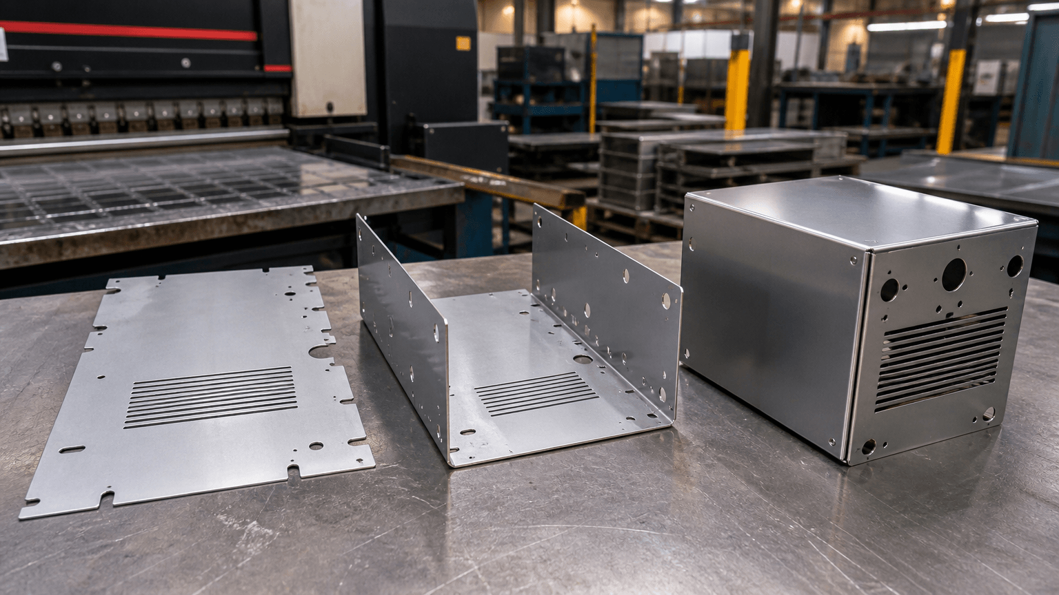
Custom sheet metal parts are made-to-order components cut and/or formed from sheet or plate to match an OEM drawing, 3D model, or functional specification. They range from flat panels and bent brackets to enclosure sections, cabinets, frames, display structures, and multi-part welded assemblies. Depending on the design, fabrication may be followed by welding, finishing, hardware installation, or assembly, but these operations are not required for every part.
For an OEM buyer, the main challenge is defining enough detail for the supplier to select a workable manufacturing route and prepare an accurate quotation. Geometry, material grade, thickness, bend requirements, quantity, visible surfaces, tolerances, weld scope, finish, inspection basis, and assembly interfaces can all affect the flat pattern, cutting method, forming sequence, joining operations, and final inspection.
What Counts as a Custom Sheet Metal Part?
A custom sheet metal project may involve one flat component, a formed part, or a complete assembly built from several fabricated pieces. This distinction matters during quotation because a mounting panel with holes and slots follows a very different route from a welded cabinet with doors, hardware, visible surfaces, and defined assembly interfaces.
- Cut-only parts: panels, blanks, mounting plates, covers, and profiles that remain flat.
- Cut-and-bent components: brackets, angles, channels, trays, guards, and enclosure sections.
- Welded assemblies: frames, bases, housings, cabinets, racks, and equipment structures made from separate fabricated pieces.
- Finished or assembled products: fabricated parts with a specified coating or polished surface, installed hardware, doors, hinges, panels, or approved supplied components.
These categories represent different levels of manufacturing scope. A stainless steel cover, for example, may need only cutting, edge preparation, bending, and a specified surface treatment. A frame may require cutting, forming, welding, alignment checks, finishing, and assembly. Neither route should be assumed from the phrase “custom sheet metal parts” alone.
For a broader view of products containing multiple fabricated components, explore sheet metal fabrication for equipment structures and assemblies.
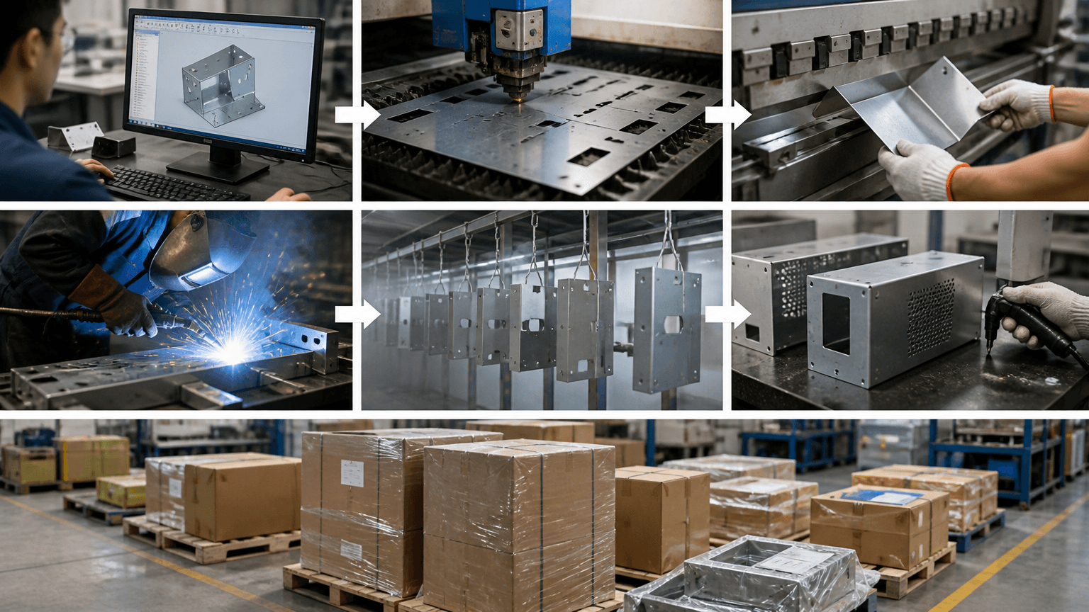
How Custom Sheet Metal Parts Move from CAD to Packing
The production sequence should follow the design rather than a fixed list of services. Establishing the route before material is cut helps identify drawing conflicts, inaccessible bends, unclear finish boundaries, and assembly issues that could otherwise become more difficult to resolve later.
- Drawing and model review. The supplier reviews the 2D drawing, available 3D CAD data, revision, material callout, quantity, finish, tolerances, and assembly notes. Any conflicts between the drawing and model should be resolved before production.
- DFM review and flat-pattern development. Where forming is required, the supplier evaluates bend radii, bend allowances, reliefs, hole locations, flange access, tooling access, grain direction where relevant, and the intended bend sequence. The formed geometry is then translated into a manufacturable flat blank.
- Programming and blank production. Outer profiles and internal features are programmed for laser cutting, CNC punching, or another selected process appropriate to the material, thickness, feature geometry, quantity, and downstream operations.
- Deburring or edge preparation. Edges are treated where needed for safe handling, fit, welding, coating, appearance, or assembly. Edge preparation is a separate requirement rather than an automatic result of cutting.
- Forming. Bending converts the blank into the specified angles, channels, trays, covers, or enclosure sections. The sequence matters because a completed flange can restrict access for a later bend.
- Joining and hardware installation. Separate parts are welded or mechanically fastened only when the product design requires joining. Specified studs, nuts, inserts, hinges, or other hardware may also be installed at this stage.
- Finishing. Powder coating, polishing, brushing, plating, or another specified treatment follows the necessary fabrication and surface preparation. Cosmetic faces, finish direction, coating boundaries, and masking areas should be defined before finishing begins.
- Inspection, final assembly, and packing. Parts are checked against the agreed drawing and inspection basis. If included in the manufacturing scope, they are then assembled, protected, labeled, and packed for shipment.
For more detail on the profile-cutting stage, review the metal laser cutting process.
Where Each Fabrication Operation Fits
Cutting, forming, joining, finishing, and assembly solve different manufacturing problems. Although several may appear in the same production route, each must be matched to a specific feature or requirement. Treating them as interchangeable can leave important scope details undefined during quotation.
| Operation | Role in the route | Points to define |
|---|---|---|
| Laser cutting | Produces programmed two-dimensional outer profiles, holes, slots, and internal features where the material and thickness are suitable. | Material, thickness, profile detail, edge requirements, visible faces, and the needs of later bending or welding. |
| CNC punching | Creates programmed holes, repeated sheet features, and certain formed features when the geometry and available tooling make punching appropriate. | Feature shape, spacing, tooling suitability, surface marking concerns, quantity, and any required formed features. |
| Bending | Converts flat blanks into angles, brackets, channels, trays, covers, and enclosure panels. | Bend direction, angle, internal radius, flange geometry, reliefs, formed datums, and grain direction where relevant. |
| Welding | Joins separate components into frames, cabinets, housings, bases, or other assemblies. | Joint locations, weld extent, access, appearance, distortion-sensitive features, post-weld dimensions, and finishing expectations. |
| Powder coating | Adds a specified post-fabrication coating when the appearance or service requirement calls for it. | Color or approved reference, texture, visible faces, masking, threads, grounding points, and acceptance criteria. |
| Polishing or brushing | Creates a specified surface appearance or directional finish on visible metal. | Cosmetic faces, finish direction, weld blending, handling protection, and any approved comparison sample. |
| Assembly | Combines fabricated parts with specified hardware, panels, doors, machined components, or other approved items. | Bill of materials, assembly drawing, fastening method, interface dimensions, fit checks, and supplied-component responsibility. |
A machined insert or mounting block can be installed in a fabricated enclosure, but CNC machining remains a separate subtractive process. Its dimensions and attachment interface must be coordinated with the cut, formed, welded, and finished sheet metal components.
See how bending converts flat blanks into formed sheet metal parts for additional forming context.
Design Details to Resolve Before Prototype Release
A design may contain enough information for an initial quotation yet still need changes before it can be formed, joined, finished, or assembled consistently. Reviewing the following details before prototype release gives engineering, procurement, and manufacturing teams a clearer basis for discussing process routing and inspection.
- Material definition: State the material grade, temper or condition where relevant, sheet thickness, and required surface state. General labels such as “aluminum” or “stainless steel” may not identify the intended material sufficiently. Aluminum, stainless steel, mild steel, galvanized steel, copper, and brass also require project-specific grade and finish confirmation.
- Formed geometry: Define bend angles, bend directions, internal radii, reliefs, flange dimensions, and dimensions that apply after forming. Bend deduction and related flat-pattern values must reflect the selected material, thickness, tooling, radius, and production method rather than a universal assumption.
- Features near bends: Review holes, slots, cutouts, and inserts located close to formed areas. Their relationship to a bend can affect deformation, tooling access, and final alignment.
- Datums and tolerances: Separate dimensions that control fit or function from general dimensions. Identify the datum structure and whether each critical requirement applies to the flat, formed, welded, coated, or assembled condition.
- Weld and assembly scope: Mark joints, weld extent, access requirements, installed hardware, mating interfaces, and fit relationships. Account for tolerance accumulation across multiple bent or joined components.
- Cosmetic surfaces: Identify visible faces, finish direction, acceptable handling areas, weld appearance, coating boundaries, masking locations, and surfaces that require protection during packing.
- Inspection basis: State which characteristics require measurement, reporting, appearance review, or fit verification. Supplier certifications do not replace the dimensional, material, cosmetic, safety, or regulatory requirements specified for the part.
Moving from Prototype Review to Batch Production
A prototype should do more than demonstrate overall appearance. Before production quantities are released, it can help the buyer and supplier confirm the bend sequence, flange access, hole alignment, hardware location, weld access, finish appearance, mating-part fit, and assembly interfaces.
Design review → prototype fabrication → fit and appearance review → documented changes → approved revision → first-piece alignment → batch production.
For an enclosure, an illustrative review could include panel alignment, hinge position, fastener access, door fit, and clearance for internal components. The actual checks must follow the product design; this example is not a universal enclosure inspection plan.
Before batch production begins, freeze the approved drawing revision, material callout, finish, cosmetic instructions, inspection basis, assembly configuration, and packaging method. Change control should distinguish between documentation-only updates and revisions that affect the flat pattern, bending sequence, joining setup, finishing mask, assembly interface, or inspection plan.
First-piece or first-article alignment should focus on characteristics important to fit, function, appearance, and downstream assembly. The scope and reporting method must be agreed for each project. Yishang supports prototype review and batch production. Its ISO and RoHS certifications provide supplier-level context, but they do not independently prove that every part satisfies a customer’s dimensional, electrical, safety, or regulatory specification. Buyers can also review the role of inspection and quality control in custom metal production.
Choose a Process Route by Geometry and Product Scope
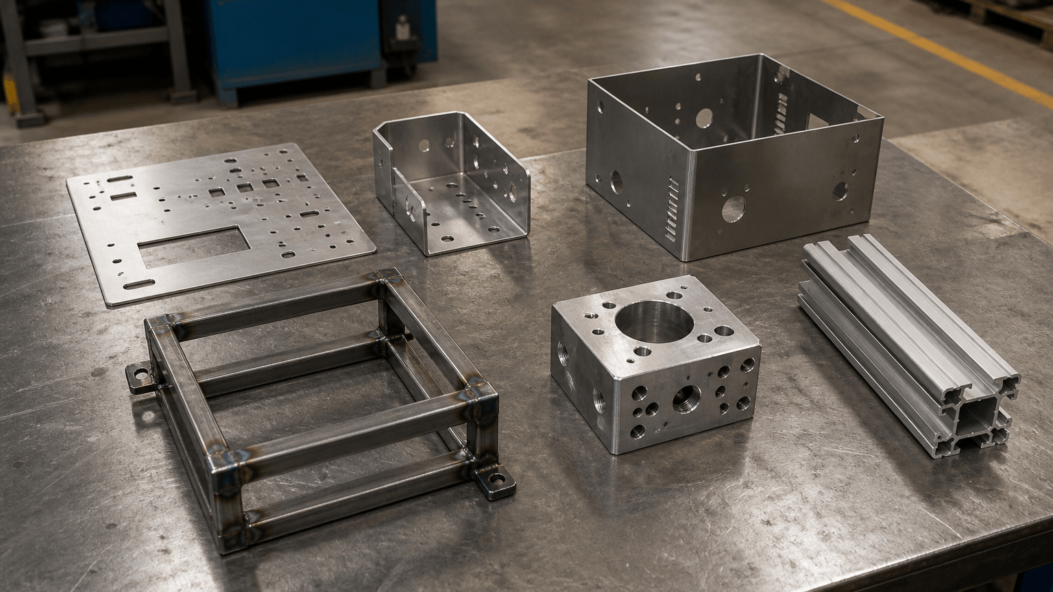
The right route depends on more than the base material. Buyers should consider geometry, quantity, appearance, structural needs, tooling, finishing, and assembly strategy when deciding whether the project suits cut-only sheet metal, formed components, a welded assembly, or a different manufacturing process.
| Part requirement | Route to evaluate | Primary review focus |
|---|---|---|
| Flat profile, blank, or mounting panel | Cut-only sheet metal | Profile geometry, internal features, edge condition, flatness requirement, finish, and quantity. |
| Bracket, channel, tray, or cover | Cutting and bending | Bend radii, reliefs, flange access, hole placement, bend sequence, and formed dimensions. |
| Enclosure or cabinet | Formed components with fastening or welding | Seams, doors, hardware, mounting interfaces, visible faces, finish, and assembly sequence. |
| Frame, base, rack, or display structure | Welded fabricated assembly | Joint access, alignment, distortion-sensitive interfaces, structural path, finishing, and shipping configuration. |
| Solid geometry, deep pocket, bore, or machined interface | CNC machining | Subtractive production from stock, feature access, material removal, and any interface with a separate fabricated assembly. |
| Constant cross-section | Extrusion | Profile geometry, tooling, material, secondary cutting or machining, finish, and joining requirements. |
| Suitable cast geometry at the planned production volume | Die casting | Tooling, alloy, wall design, volume, finish, and secondary operations. |
| Plastic housing or component | Injection molding | Polymer properties, tooling, volume, wall design, appearance, and assembly interfaces. |
| Complex prototype or low-volume form poorly matched to conventional tooling | 3D printing | Material behavior, surface, accuracy, build orientation, and whether the output represents production intent. |
No route is universally preferable. A product may legitimately combine bent sheet metal, separately machined interfaces, extruded rails, purchased hardware, and plastic components, provided the drawings define how those parts locate, fasten, and function together.
Frequently Asked Questions
These questions address the drawing, tolerance, finish, quantity, and prototype details that commonly shape an RFQ for custom sheet metal parts.
What information is needed to quote custom sheet metal parts?
Provide a revision-controlled 2D drawing and, where available, a 3D CAD model. State the material grade, thickness, prototype and production quantities, finish, visible faces, required processes, critical tolerances, weld or assembly notes, inspection expectations, and packaging requirements. Clearly identify any supplier-proposed details that require buyer approval.
Can one supplier deliver both individual components and welded assemblies?
Yes, when the supplier’s verified manufacturing scope covers the required work. The quotation should state whether material, cutting, deburring, forming, welding, hardware, finishing, inspection, assembly, and packing are included. A quoted price for an individual formed part should not be assumed to cover the complete welded product.
How should tolerances and cosmetic requirements be specified?
Use general tolerances for noncritical features, then identify the dimensions that control fit, function, or alignment. Define the datums and state whether each requirement applies before or after forming, welding, coating, or assembly. Mark visible faces, finish direction, color or approved reference, masking areas, weld treatment, and handling protection. Coating buildup should also be considered at threads, holes, grounding points, and mating interfaces.
How does sheet metal fabrication differ from CNC machining?
Sheet metal fabrication primarily cuts and forms sheet or plate, with joining and finishing added when specified. CNC machining removes material from stock to produce features such as pockets, bores, threads, and precision interfaces. They are distinct processes, although a machined component can be fastened—or welded where technically appropriate—into a separately fabricated assembly.
Planning a prototype or production RFQ? Send the available drawings and CAD files with the material grade and thickness, prototype and production quantities, finish details, visible-face requirements, critical dimensions and tolerances, inspection expectations, and assembly or packing notes. Yishang can review the information for process routing, manufacturability, prototype alignment, finishing scope, and batch-production planning before preparing an OEM or ODM quotation.