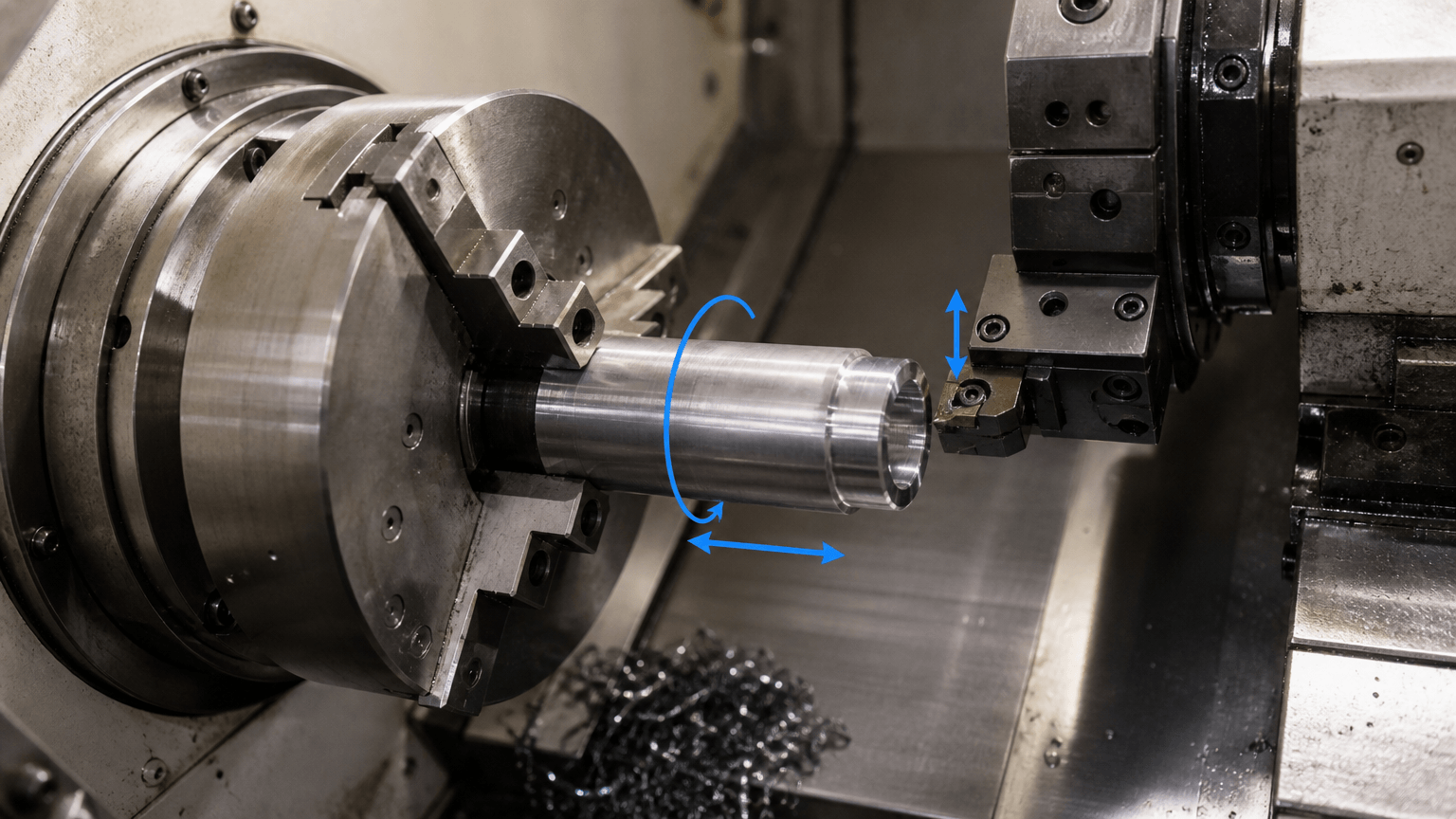
An industrial lathe holds and rotates a workpiece while a controlled cutting tool removes material. Axial and radial tool movement makes turning well suited to cylindrical features such as shafts, pins, bushings, rollers, threaded adapters, spacers, and round housings. Milling is different because the cutter provides the primary rotation. For a buyer reviewing a drawing, the practical question is whether the proposed lathe setup can grip, support, cut, and inspect the required geometry. Off-axis holes, flats, slots, and pockets may need live tooling, another machine, or a separate setup.
How an industrial lathe cuts a part
Turning is usually the first process to evaluate when a drawing shows several diameters, shoulders, bores, grooves, or threads around a common centerline. It is a subtractive machining process commonly applied to bar, tube, forgings, castings, and near-net-shape blanks. The spindle rotates the workpiece while the tool feeds parallel to the axis, toward or away from the axis, or along a programmed path. That motion creates rotational geometry, while the selected machine configuration determines whether secondary features can be completed before the part is unclamped.
Common turning operations include facing, which creates a flat end face and length reference; external turning, which cuts outside diameters and shoulders; boring, which enlarges or finishes an internal hole; grooving, which forms narrow recesses; threading, which produces internal or external threads through coordinated spindle and tool movement; taper turning, which changes diameter along the axis; drilling on center, which creates an axial hole aligned to the spindle; and parting, which separates the finished component from remaining stock.
A lathe favors features that share a rotational axis. Several coaxial diameters on a shaft may be machined in one setup, helping preserve their relationship to the same datum axis. A pocket, flat, or cross-hole away from that axis belongs to a different feature family. It may be possible on a turn-mill machine with the right axes and powered tools, but the label “CNC lathe” alone does not prove that capability.
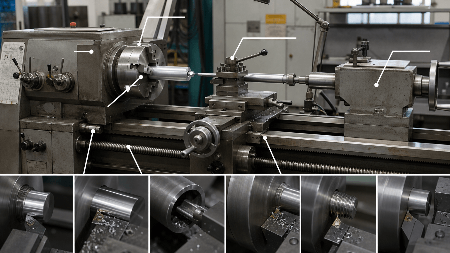
Core machine elements and work support
A feasible turning route depends on more than whether the part appears to fit inside a machine envelope. The blank must be held securely, supported where needed, and left accessible to the cutting tools. The bed is the structural base that guides the cutting system. The headstock supports the spindle drive, and the spindle transmits rotation to the workholding device. A chuck can hold individual blanks or formed stock, while a collet can suit compatible bar or round parts where the gripping condition is appropriate.
On a conventional engine lathe, a carriage carries and moves the tool post. On a CNC lathe or turning center, a turret typically indexes among installed tools and follows programmed tool paths. Available components vary by machine, so a buyer should not assume a specific number of tool stations, a bar feeder, a sub-spindle, live tooling, Y-axis motion, or automated part handling without confirmation.
A tailstock may hold a drill or support the free end of the workpiece with a center. Steady rests and follow rests can help control deflection on slender work, but they also occupy space and can restrict tool access. Workholding must grip the part firmly enough for cutting while avoiding distortion of thin walls, finished surfaces, or locating features.
Match the part geometry to the lathe configuration
Industrial lathe selection is not a good-better-best ranking. It is a geometry, setup, and production-pattern decision. A prototype shaft, a bar-fed threaded insert, a slender pin, and a heavy short housing may all involve turning, but they do not point to the same machine layout. The matrix below gives buyers a practical way to compare options before asking a supplier to confirm the actual setup.
| Configuration | Operating principle and suitable geometry | Setup implications | Questions to verify |
|---|---|---|---|
| Conventional engine lathe | Manual control of spindle rotation and tool movement for straightforward rotational work, development, repair, and suitable low-volume parts. | Results depend heavily on setup and operator control. Off-axis features usually move to other equipment. | How the part will be held, supported, measured, and controlled for the required quantity. |
| CNC lathe or turning center | Programmed tool paths for repeated external and internal rotational features. | Can improve repeatability and cycle control, but automation and secondary-feature capability vary by machine. | Actual axes, spindle arrangement, turret tooling, loading method, workholding, and support plan. |
| Turn-mill machine | Combines turning with powered tools for selected milling, drilling, flats, slots, and cross-holes. | May reduce handling when supported features can be completed before unclamping. | Which features can be reached in one setup and which still require reclamping or another machine. |
| Swiss-type machine | Supports slender bar close to the cutting zone, commonly through a guide arrangement. | Can help suitable long, small-diameter parts, but the route must match the stock, geometry, and quantity pattern. | Length-to-diameter relationship, stock compatibility, feature access, material behavior, and inspection approach. |
| Vertical lathe | Uses a vertical spindle orientation commonly associated with heavy, short-and-wide rotational work. | Orientation can assist workholding for suitable parts, but the machine name does not establish usable capacity. | Blank support, chucking method, tool clearance, feature access, runout control, and deformation risk. |
Published machine capacity is not the same as usable capacity for a specific setup. Chuck jaws, fixtures, tool holders, tailstock access, support rests, and workpiece projection all consume space. Buyers should confirm finished diameter and length, stock form, spindle or bar-feed constraints, tool access, and support method against the drawing.
How material and geometry change the turning plan
Two similarly sized turned parts can require different tools, workholding, cooling, and cycle time. Steel can affect tool life and heat control. Stainless steel may introduce work-hardening and chip-control concerns. Aluminum can be prone to built-up edge and burrs. Brass has different cutting and chip behavior. Engineering plastics may expand with heat, deflect during cutting, or deform under excessive clamping. These issues depend on grade, tooling, machine condition, coolant or lubrication, and setup rather than a universal feed or speed chart.
Geometry often matters as much as material. A shaft with a high length-to-diameter ratio can deflect or chatter when extended from the chuck. Tailstock support, centers, steady rests, staged stock removal, or revised workholding may help. Thin-wall bushings and tubes can become out-of-round under clamping force or shift as material is removed from inside and outside surfaces. Soft jaws, collets, controlled clamping force, balanced roughing, and separate finishing passes are possible responses, not automatic guarantees.
Deep bores require long internal tools, which reduce rigidity and complicate chip evacuation. Interrupted cuts from cross-holes, slots, cast surfaces, or keyways repeatedly load and unload the cutting edge. Narrow grooves, internal threads, and multiple-chuck operations add access and locating challenges. If related diameters, faces, bores, and threads have critical axial or rotational relationships, machining them in one setup may reduce accumulated locating error, provided the tools can still reach the features safely.
Drawing, capability, and inspection questions
A strong capability review starts with the drawing, not a machine list. The supplier needs the material grade, stock-form assumption, finished diameter and length, tolerance requirements, thread details, surface-finish callouts, lot size, and any inspection documentation required by the buyer. Bar-fed repeat production, individually chucked blanks, forgings, castings, and pre-cut tubes create different loading, support, and setup demands.
Critical dimensions need clear datums and relationships. Dimensional tolerance defines acceptable variation in size or location. Runout evaluates variation as a feature rotates relative to a datum axis. Coaxiality concerns the relationship between feature axes. Concentricity, where genuinely applicable, should not be used casually as a substitute for runout or coaxial control. Straightness, thread form and fit, and surface roughness should be specified only where they matter to function, assembly, sealing, wear, or appearance.
Inspection should match the characteristic being controlled. Depending on the drawing, suitable examples may include micrometers for accessible outside dimensions, bore gauges for internal diameters, thread gauges for specified threads, surface-roughness instruments, rotational measurement for runout, and coordinate measurement for more complex feature relationships. Method availability and suitability should be confirmed for each project. Buyers can use Yishang’s quality control information as a starting point for discussing inspection stages and documentation.
The drawing should specify the required result rather than an unnecessarily restrictive machine brand or model. Suppliers evaluating CNC-machined and turned components still need to confirm the project-specific equipment, workholding, process sequence, and inspection method.
Cost, lead time, and mixed-process assembly
A turned-part quotation reflects the complete production route, not cutting time alone. Cost and lead-time drivers can include raw stock, programming, setup, workholding, special tooling, cutting time, tool wear, deburring, finishing, inspection, secondary setups, and quantity. A repeat part made from compatible bar stock may allow automated loading on suitable equipment. A casting, forging, or individually chucked blank may require preparation, orientation, and handling for every component.
Off-axis features, deep internal geometry, tight related-feature tolerances, post-treatment finishing, and extensive inspection can add operations. Turn-mill equipment may involve more programming and tooling, yet it can reduce total handling when turning and supported secondary features are completed before the part is unclamped. The relevant comparison is the full route and setup count, not the machine category in isolation.
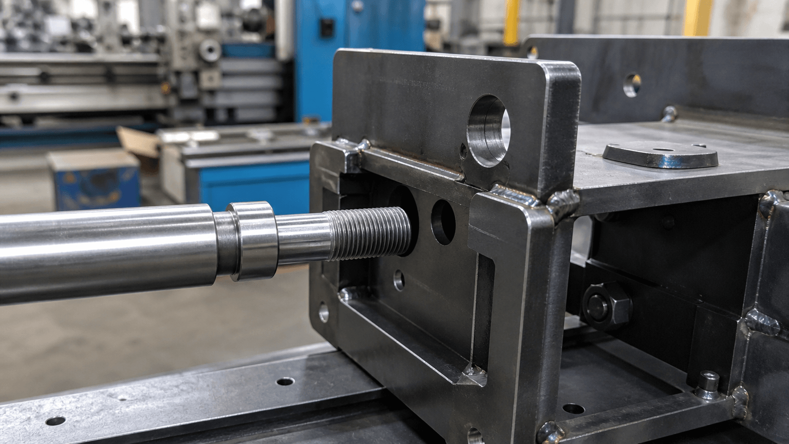
Many industrial products combine turned components with sheet metal enclosures, brackets, frames, or welded structures. Turning and sheet metal fabrication remain separate processes within that route. Turned parts can serve as shafts, spacers, pivots, bushings, locating pins, threaded bosses, and inserts. Laser cutting creates sheet or plate profiles; bending forms them; welding joins compatible components; finishing applies coating or surface treatment; and assembly brings the parts together through fasteners, fits, welds, or other specified joining methods.
A machined component can become a critical interface inside a fabricated product. The complete design should account for mating datums, hole clearance, press-fit or slip-fit intent, fastener access, weld access, coating allowance, and assembly sequence. Welding can distort surrounding structures, and coating can change effective clearance at mating features. Metal spinning is also distinct from turning: it rotates sheet over a mandrel and forms the material rather than cutting a solid or tubular blank in the conventional turning sense.
Request a mixed-process manufacturability review
If your product combines turned parts with an enclosure, bracket, frame, or welded assembly, send Yishang the complete drawing package for early review. Include 2D drawings and available 3D files, material grade and stock assumptions, prototype and batch quantities, critical diameters, lengths, threads, datums, runout or coaxiality requirements, surface-finish callouts, drawings of the mating assembly, surface treatment, inspection documentation, packaging, and destination. Yishang supports OEM and ODM project review, prototyping, and batch production; any project-specific industrial lathe capacity and inspection requirements should be confirmed against the submitted drawings.
Where RFQ Assumptions Create Cost and Production Risk
Many sheet metal fabrication problems begin before production starts. If drawings, tolerances, finish expectations, material grades, or assembly requirements are unclear, suppliers may quote based on different assumptions. That can make prices difficult to compare and may lead to rework, cosmetic rejection, assembly misalignment, or production delays later.
For OEM buyers, the goal is not simply to request the lowest price. The goal is to make sure each supplier is quoting the same manufacturing reality. Before confirming an order, clarify which dimensions are fit-critical, which surfaces are cosmetic, whether prototypes must match batch-production conditions, and how finished parts will be inspected.
Frequently Asked Questions
What industrial lathe details should buyers define before requesting a quote?
Buyers should define the functional requirement, drawing notes, critical dimensions, material or process expectations, and any inspection points related to industrial lathe. This helps suppliers quote the same manufacturing scope instead of making different assumptions.
How can RFQ details affect cost, fit, or lead time?
RFQ details can change tooling, forming, welding, finishing, inspection, or rework requirements. If buyers do not clarify it early, two supplier quotes may look comparable while covering different production risks.
Why should drawing requirements be reviewed before prototype approval?
drawing requirements may look acceptable on a single sample but become harder to control during batch production. Buyers should confirm whether the prototype reflects the same process, finish, and inspection conditions expected for production.
What inspection points matter most for industrial lathe projects?
Important inspection points usually include fit-critical dimensions, holes or mating areas, cosmetic surfaces, finish build-up, welded or formed features, and any dimensions that affect downstream assembly. These points should appear in the RFQ or drawing notes.
How can buyers reduce prototype approval risk before batch production?
Buyers can reduce risk by clarifying drawings, locking key material and finish assumptions, defining inspection timing, approving a representative sample, and confirming which dimensions or surfaces require tighter process control.
How can Yishang help review industrial lathe requirements?
Yishang can review drawings, RFQ notes, material requirements, tolerance expectations, finish details, samples, and assembly needs to identify unclear assumptions before quoting or batch production.