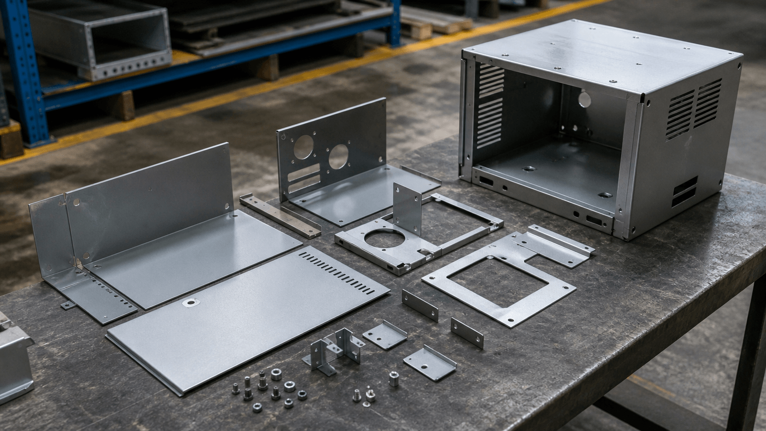
A fabricated part is one manufactured component. A fabricated assembly combines two or more components through welding, fastening, bonding, or another defined joining route. A laser-cut and bent bracket is a part; an enclosure made from formed panels, brackets, hinges, and hardware is an assembly. Even when every component meets its part drawing, assembly fit still depends on shared datums, accumulated variation, joint design, finishing sequence, and the condition in which inspectors evaluate the product.
For an OEM buyer, this distinction becomes important when a purchase changes from loose brackets or panels to a cabinet, welded frame, display structure, or fitted enclosure. The delivery scope determines who controls joining, hardware installation, interface fit, final inspection, packaging, and the labor needed to prepare the product for equipment installation.
An assembly may contain fabricated sheet metal parts, purchased fasteners, hinges, seals, electrical items, or components produced through other processes. For example, an assembler may attach a CNC-machined boss to a formed panel. Machining and sheet metal fabrication remain distinct operations, but the assembly documentation must define their interface.
From Flat Sheet to an Assembled Product
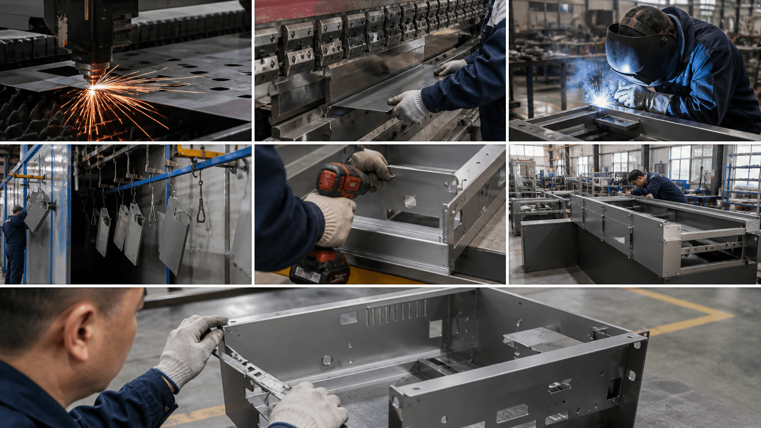
When an OEM orders a completed enclosure rather than loose panels, the manufacturing route must extend beyond cutting and bending. Process planning must account for joint access, coating-sensitive interfaces, hardware installation, functional checks, and protection of the finished product during shipment.
- Drawing and model review: The manufacturing team reviews part files, assembly documents, materials, interfaces, revisions, and the intended delivery state before planning the process.
- Blanking and feature creation: Laser cutting or CNC punching creates the flat profile, holes, slots, and other specified features. These operations produce blanks; they do not form or assemble them.
- Forming: Bending converts flat blanks into brackets, channels, covers, panels, and one-piece enclosure bodies. Tooling, bend sequence, material behavior, and the relationship between holes and bends affect final geometry.
- Edge and surface preparation: Drawings may specify deburring, cleaning, or local joint preparation for handling, joining, appearance, or finishing.
- Joining: Manufacturers may connect components by welding, spot welding, riveting, threaded fasteners, press-fit hardware, structural adhesive, or a defined combination.
- Surface finishing: Powder coating, polishing, or another specified treatment establishes the required surface condition. Finishing is distinct from cutting, forming, and joining, although its timing affects later operations.
- Hardware installation and final assembly: The assembly team installs hinges, inserts, doors, seals, removable panels, fasteners, and purchased components to reach the specified delivery state.
- Verification and packing: Inspectors check part characteristics, joints, finish, assembly fit, and required functions before packing.
The order can change by project. Weld areas generally need access before finishing, while threads, grounding points, and close-fitting interfaces may require masking. Installers may fit some press-fit hardware before coating and add finished removable panels later to limit handling damage. These coordinated stages form the route for custom sheet metal structures and assemblies.
Documents That Control the Part and the Assembly
A buyer can release several accurate part files and still leave the intended relationships between components unclear. Once the scope includes assembly, the manufacturing package must control component position, joint construction, hardware, revisions, interfaces, and the state in which inspectors will assess fit. A 3D model supports interpretation but does not automatically supply missing tolerances, joint requirements, or finish notes.
| Document or requirement | Information it should control | Consequence if incomplete |
|---|---|---|
| Part drawing | Material designation, thickness, geometry, bends, holes, dimensions, tolerances, edge requirements, and part-level finish | A part may be acceptable alone but incompatible with mating components. |
| Assembly drawing | Component positions, orientation, assembly datums, interface dimensions, joints, hardware, access requirements, and acceptance state | Manufacturing teams may interpret location, joining sequence, or assembled verification differently. |
| Bill of materials | Part numbers, quantities, descriptions, purchased items, and matching revision identifiers | Incorrect or mismatched components may enter the build. |
| Joint and hardware callouts | Weld location and extent, rivets or fasteners, adhesive areas, hardware orientation, and installation instructions | The joint may not meet the intended load path, appearance, access, or service requirement. |
| Finish requirements | Finish type, appearance, coverage, masking, protected interfaces, and process sequence | Finish buildup may interfere with threads, fits, electrical contact, or visible surfaces. |
Revision control must connect the part files, top-level assembly drawing, and controlled BOM. If a bracket pattern changes while its mating panel remains at an earlier revision, each file may look complete even though the package defines an inconsistent assembly.
Critical dimensions also need a stated inspection condition. A mounting pattern, panel gap, hinge location, or equipment interface might require evaluation before coating, after finishing, or on the completed assembly. The drawings should make that state explicit.
Selecting a Joining Route
The joining method determines more than whether components remain connected. It can affect distortion, visible surfaces, process order, tool access, sealing, serviceability, and inspection. A permanent frame and a removable equipment cover therefore require different decisions even when their sheet metal parts are similar.
The methods below are general engineering options. Their inclusion does not mean every manufacturer offers every method, and no method is universally strongest, least expensive, or most appropriate.
| Method | When it may be considered | Items to define or review |
|---|---|---|
| MIG or TIG welding | A permanent metal joint, structural load path, continuous joint, or blended appearance is required | Material and thickness compatibility, joint design, access, heat input, distortion, marking, fixturing, sequence, and finish restoration |
| Spot welding | Overlapping sheet components can accept discrete joining points and equipment can reach the joint | Overlap geometry, electrode access, material stack, surface condition, point locations, indentation, and coating sequence |
| Riveting | Welding heat is undesirable or a permanent mechanical connection suits the design | Hole preparation, edge distance, grip range, installation access, protrusion, finish buildup, and head appearance |
| Threaded fasteners | The product requires disassembly, adjustment, replacement, or field service | Tool access, tightening direction, thread engagement, locking method, hardware retention, and finished clearance |
| Press-fit hardware | Sheet requires captive threads, studs, standoffs, or another installed feature | Hardware and sheet compatibility, prepared hole condition, installation direction, clearance, local distortion, and finishing sequence |
| Structural adhesive | The joint can distribute loads over a bonded area, or the design should avoid visible fasteners and concentrated heat | Substrates, surface preparation, bond gap, cure conditions, environment, loading mode, inspection, and service conditions |
Many products combine methods. A cabinet could use a welded body, press-fit nuts for internal mounting, threaded fasteners for removable covers, and hinges for a service door. Aluminum, mild steel, galvanized steel, and stainless steel may also respond differently to forming, joining, corrosion exposure, weight requirements, and finishing. Engineers evaluating a welded route can review Yishang’s welding service while defining project-specific joints and acceptance criteria separately.
Datum Chains, Distortion, and Finished Interfaces
Fit problems often emerge only when the OEM brings several acceptable parts together. In an illustrative panel-and-bracket assembly, the designer may locate panel holes from an edge, bracket holes from a bend, and the equipment interface from an assembled centerline. Variation can accumulate in different directions even though each isolated dimension remains within its stated limits.
A functional datum strategy starts with the surfaces and features that locate the completed product. The assembly definition should identify what establishes location and orientation and which dimensions control mounting, door, or panel alignment. Slots, floating hardware, and intentional clearance can accommodate expected variation, but designers should treat them as planned features rather than production corrections.
Forming contributes to the datum chain. Sheet thickness, material direction, inside bend radius, tooling, K-factor assumptions, bend deduction, and springback can influence feature positions. Their effects depend on the selected material, geometry, equipment, and setup, so one universal bend rule cannot cover every project.
Welding can introduce additional movement. Joint design, sequence, heat input, fixturing, restraint, and cooling behavior may affect squareness or move mounting features. A fixture locates components during joining, but the design and inspection plan must still address possible distortion.
Powder coating and other deposited finishes add material at interfaces. Buildup may affect slip fits, hinges, threads, grounding points, panel gaps, and mating faces. Drawings should state whether inspectors evaluate relevant dimensions and fit before finishing, after finishing, or at both stages.
Verification and Delivery Scope
An OEM purchasing a completed cabinet needs different evidence from one purchasing loose brackets. Part-level measurements do not establish that the cabinet is square, its doors move correctly, or its mounting pattern fits the intended equipment. Part inspection and assembly verification are connected but not interchangeable.
Part-level checks may address specified material, thickness, cut features, formed dimensions, hole locations, and surface condition. In-process checks can address orientation, joint placement, hardware installation, and features that later operations will make inaccessible.
Final verification may cover overall dimensions, squareness, hole alignment, interface fit, hardware presence, door or panel movement, visible joint condition, finish coverage, and cosmetic condition where specified. The buyer should define critical characteristics, applicable revisions, inspection state, sampling expectations, documentation, traceability, and nonconformance disposition. A requested prototype or first-piece review can help validate fit, appearance, process sequence, and drawing interpretation before batch production, but it does not replace controlled production documents.
Delivery scope also changes OEM workload. Loose parts require identification, protective packaging, incoming inspection, storage, kitting, and internal assembly. Subassemblies transfer selected joining or hardware operations while preserving access for equipment installation. Completed assemblies transfer more integration work to the manufacturer, making final fit, movement, appearance, and function more important to define.
Packaging should account for finished surfaces, protruding hardware, hinges, moving elements, and exposed interfaces. Removable components can remain in the BOM while the manufacturer packs them separately to avoid contact or transit damage. Buyers can review Yishang’s assembly service and quality control information when evaluating delivery scope.
Where RFQ Assumptions Create Cost and Production Risk
Many sheet metal fabrication problems begin before production starts. If drawings, tolerances, finish expectations, material grades, or assembly requirements are unclear, suppliers may quote based on different assumptions. That can make prices difficult to compare and may lead to rework, cosmetic rejection, assembly misalignment, or production delays later.
For OEM buyers, the goal is not simply to request the lowest price. The goal is to make sure each supplier is quoting the same manufacturing reality. Before confirming an order, clarify which dimensions are fit-critical, which surfaces are cosmetic, whether prototypes must match batch-production conditions, and how finished parts will be inspected.
Frequently Asked Questions
These questions address common drawing, tolerance, finish, and purchasing-scope issues that arise when a project moves from individual parts to an assembled product.
Is a welded frame one fabricated part or a fabricated assembly?
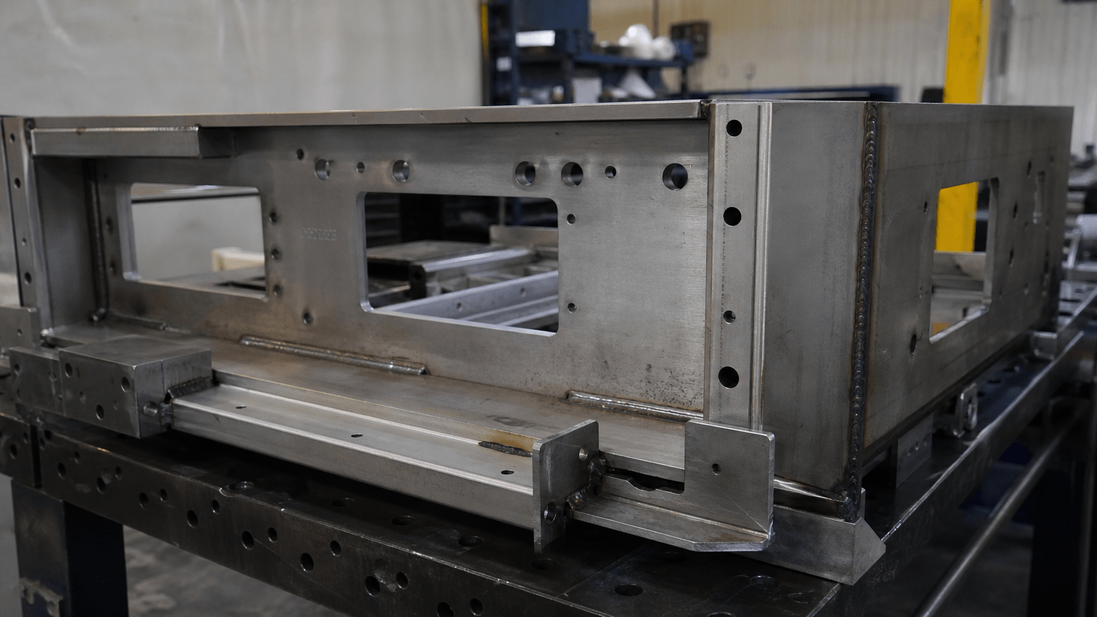
A welded frame is normally a fabricated assembly because it combines two or more components. A buyer may purchase it under one line item, but its constituent parts, weld requirements, datums, and assembly-level dimensions still need control.
Can fabricated assemblies include machined parts, hinges, or purchased components?
Yes. They can include sheet metal parts, machined items, hinges, fasteners, seals, electronics, cast parts, molded components, or extrusions. The assembly drawing and BOM define their relationships, while the original manufacturing processes remain distinct.
Should powder coating occur before or after welding and final assembly?
The sequence depends on joint access, heat exposure, masking, corrosion and appearance requirements, hardware, and service needs. Welding often precedes coating, while installers may add selected hardware or removable panels later. Project documents should define the sequence and protected interfaces.
Why can holes aligned in separate CAD files fail to align after bending and welding?
The files may use different datums or omit the combined effects of forming, springback, joint position, weld distortion, and finish buildup. The engineering team should evaluate alignment at the top-level assembly against the functional interface and intended inspection state.
What is the difference between an assembly drawing and a bill of materials?
An assembly drawing shows component location, orientation, joining, datums, and assembled interfaces. A BOM identifies the required items, quantities, descriptions, purchased components, and revisions. Both should remain under matching revision control.