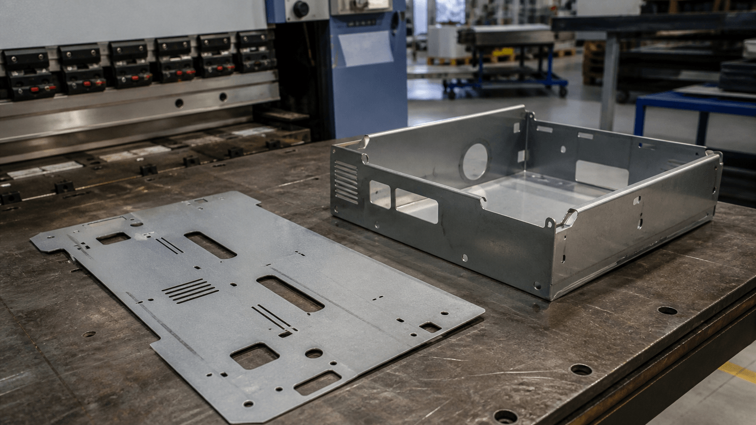
Standard sheet metal works commonly refers to routine operations performed on sheet stock, including cutting, punching, bending, joining, finishing, and assembly. For a buyer, however, the phrase identifies only a broad manufacturing scope. It is not a universal standard or a fixed production sequence.
A fabricator still needs the material grade, sheet thickness, tolerances, finish, inspection requirements, hardware, and acceptance criteria. These details must come from the drawing, purchase specification, referenced technical standards, and project-specific agreement.
What “Standard” Means in Sheet Metal Work
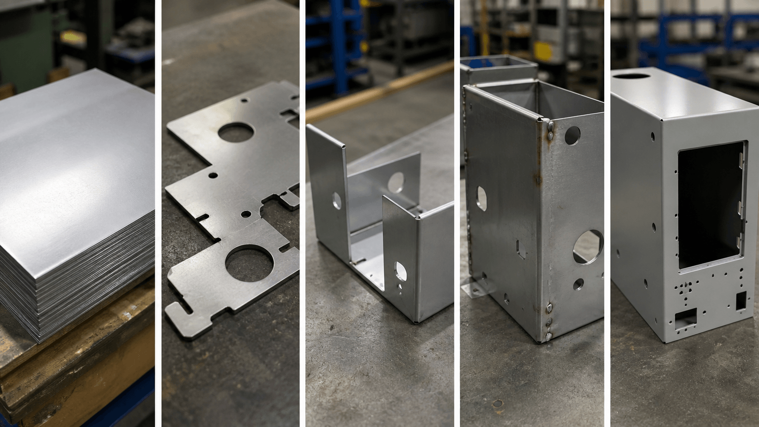
When a buyer uses this phrase at the start of a project, it usually points the fabricator toward a family of operations that converts flat sheet into parts or assemblies. A possible route begins with a cut or punched blank, continues through bending and joining, and may then include finishing, inspection, assembly, and packing. The actual route depends on the product, so not every part passes through every stage.
In this context, standard generally means common or routine. It does not indicate that every fabricator follows the same route or supports the same materials, thicknesses, dimensions, tolerances, finishes, equipment, or production quantities. The exact capitalized phrase can also appear as a business name in search results; this article addresses only its generic manufacturing meaning.
Three concepts need to remain separate. A fabrication operation changes the sheet or joins fabricated components. A product specification defines the required material, geometry, appearance, function, and acceptance conditions of the finished product. A published technical standard is a formally issued document governing a material, process, test, drawing convention, or product requirement when the drawing, order, or contract invokes it.
From Flat Sheet to Finished Product
The manufacturing route must follow the part geometry, material condition, quantity, joining method, appearance, and assembly function. These factors determine whether the fabricator cuts or punches the blank, how it is bent, and whether joining, finishing, or final assembly is needed. Inspection and packing likewise follow the order requirements rather than an assumed shop-wide definition of standard work.
| Operation | Role in the route | Selection considerations |
|---|---|---|
| Two-dimensional laser cutting | Cuts external profiles, internal openings, and other features from flat sheet. | May suit varied contours and mixed feature shapes. Material, thickness, geometry, edge requirements, downstream forming, and available equipment still require confirmation. |
| CNC punching | Uses controlled punch tooling to create holes, slots, repeated features, and certain formed details in sheet. | May suit geometry compatible with available tools, particularly when features repeat. Tool access, feature spacing, tooling marks, material, quantity, and later bending affect the decision. |
| Press-brake bending | Forms a cut or punched blank along defined bend lines to create flanges, channels, boxes, and related shapes. | Bend access, forming sequence, inside radius, flange dimensions, hole locations, material behavior, and tooling must be reviewed. |
| Welding | Creates metallurgical joints between separate components. It is a joining stage in some fabrication routes, not another term for cutting or forming sheet. | The drawing must establish joint locations and weld requirements. Access, heat input, sequence, and fixture strategy can affect distortion and finished geometry. |
| Mechanical joining | Connects components with specified screws, rivets, clinch hardware, inserts, or other fasteners. | Hardware type, installation direction, access, removability, and applicable performance requirements need to be defined. |
| Grinding or polishing | Treats selected surfaces or weld areas to produce a specified condition or appearance. | The required texture, direction, visible surfaces, edges, and weld treatment must be identified. This work is not an automatic consequence of welding. |
| Powder coating | Applies and cures a dry coating as a separate finishing operation after fabrication. | Color, gloss, texture, pretreatment, masking, protected interfaces, and acceptance criteria are project requirements, not properties implied by sheet metal work. |
| Assembly | Combines fabricated parts with hardware, doors, panels, brackets, or separately manufactured components. | The BOM, component orientation, fastening requirements, supply scope, and required checks should be controlled by the product documentation. |
This sequence is illustrative. A flat panel may require only cutting and inspection, whereas an enclosure may need bending, hardware installation, joining, coating, and final assembly. Finishing and assembly remain optional unless the product specification includes them.
Where Ordinary Flat-Sheet Fabrication Ends
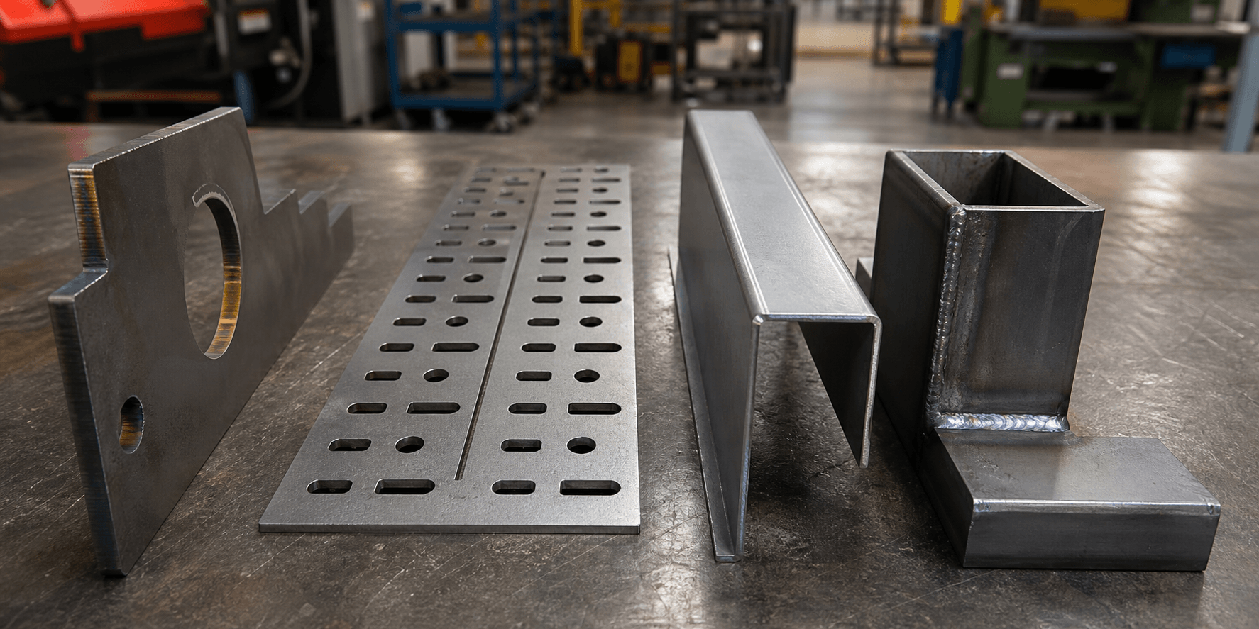
Process labels matter when buyers compare capabilities or send a drawing for review. For example, flat-sheet laser cutting creates profiles in planar stock before forming, while tube cutting works with tubular profiles and three-dimensional cutting addresses spatial geometry or formed components. These processes require different workholding, motion, access, and equipment, so capability in one does not establish capability in the others.
CNC punching also differs from stamping and deep drawing. It creates individual features with controlled tools and can produce certain formed details. Production stamping generally relies on dedicated tooling to make repeated features or forms, while deep drawing pulls sheet into a die to create a deeper hollow shape. Parts requiring these methods should not be presented as ordinary cut-and-bent components.
Press-brake bending creates discrete bends in a sheet blank. Extrusion, by contrast, forces material through a die to produce a continuous profile with a substantially constant cross-section. Die casting fills a mold with molten metal. An extruded rail or cast housing may be incorporated into a larger product, but neither is made through press-brake sheet metal fabrication.
CNC machining removes material with cutting tools and is separate from cutting, punching, and bending sheet. It may produce mounting blocks, spacers, shafts, or features that cannot be made appropriately with ordinary sheet operations. A fabricated enclosure, for example, may contain a machined mounting component. The drawing and BOM should define the interface, while the manufacturing and inspection requirements for each process remain distinct.
What the Process Terms Leave Undefined
A request for standard work can establish a broad manufacturing direction, but it cannot define the finished part well enough for process planning or acceptance. The matrix below separates what each operation tells the fabricator from the product-specific information that the buyer must provide.
| Broad request | What it tells the fabricator | What remains to be specified |
|---|---|---|
| Cut or punch the sheet | A flat blank and feature pattern are required. | Material grade and condition, thickness, profile dimensions, critical holes, cutouts, edge requirements, and applicable tolerances. |
| Bend the part | The blank must become a three-dimensional formed component. | Datums, finished dimensions, bend directions, angles, inside radii, critical flange relationships, grain direction where relevant, and drawing convention. |
| Weld the components | The assembly requires permanent joints. | Weld symbols, joint locations, size and extent, accessible sides, appearance criteria, distortion-sensitive dimensions, and areas protected from weld or spatter. |
| Apply a finish | A separate surface-treatment stage is required. | Finish system, color or texture, visible surfaces, masking, protected threads or contacts, cosmetic limits, and specified tests or acceptance criteria. |
| Assemble the product | Delivery includes more than loose fabricated parts. | BOM, hardware, orientation, fastening requirements, critical interfaces, functional checks, and responsibility for supplied components. |
| Inspect and pack | The product requires verification and shipment protection. | Acceptance characteristics, measurement methods where needed, sampling expectations, required records, labels, protective materials, packing unit, destination, and handling risks. |
Several process effects connect these requirements. Bend compensation links the flat pattern to the formed dimensions and depends on the material, thickness, radius, tooling, and process conditions. Weld sequence and fixture location can influence heat distortion, while coating buildup can affect mating surfaces, holes, threads, and electrical contact areas. Variation can also accumulate across an assembly, making a clear datum scheme and defined critical interfaces more useful than a collection of unrelated dimensions.
Inspection needs an explicit basis as well. The drawing or purchase specification should identify the dimensions, surfaces, interfaces, and cosmetic conditions that control acceptance, along with any required measurement methods, records, or sampling expectations. A published standard applies only when the controlling documentation invokes it.
How Product Form Changes the Route
Recognizable product forms help illustrate how operations interact, but the examples below are not confirmed factory capabilities or customer projects. They do not establish an available size, tolerance, material, finish, or production quantity; each combination still requires project-specific review.
Enclosures and cabinets: Cutouts, ventilation features, bends, inserts, doors, internal supports, and finishing requirements can create several linked stages. Hinge alignment, door gaps, grounding points, removable panels, masked areas, and equipment interfaces may determine which dimensions need control after assembly.
Frames and welded assemblies: Cut and formed members must provide access for joining and fit the intended fixture strategy. Welding sequence influences distortion management, while dimensional verification commonly covers mounting planes, hole patterns, diagonals, and interfaces with other equipment.
Display racks: Repeated formed components may be welded or mechanically fastened and combined with purchased hardware. Visible joint treatment, contact points, finish appearance, stability requirements, assembly configuration, and packing arrangements can all alter the route.
Panels and brackets: These parts may use only cutting, punching, and bending, but hole-to-bend relationships, insert positions, bend orientation, connector clearances, and mating dimensions still affect process selection. Laser cutting and CNC punching may both be candidates, although the choice must reflect the actual geometry and acceptance requirements.
Building a Reviewable Manufacturing Package
A controlled drawing or 3D model gives the fabricator a basis for reviewing geometry, but shape alone is not enough to plan production or prepare a reliable quotation. The documentation should identify dimensions, datums, tolerances, bend information, weld symbols, finish callouts, critical interfaces, and visible surfaces. When the supply scope includes assembly, a BOM should also define the hardware, purchased items, and separately manufactured components.
Commercial context helps confirm the route without turning the request into a generic procurement exercise. Relevant information includes quantity, prototype or production stage, destination, assembly scope, and packaging needs. A prototype review may reveal inaccessible bends, ambiguous joints, finish conflicts, or accumulated tolerances. Before batch production, approved drawings, models, BOMs, programs, and finish requirements need consistent revision control.
Yishang provides B2B-only custom manufacturing and supports OEM and ODM projects. It has more than 26 years of experience, exports to more than 50 countries, and holds ISO and RoHS certifications. These facts do not confirm support for every material, thickness, tolerance, size, finish, or quantity; capability and process scope require project-specific review.
For a custom sheet metal fabrication scope review, provide the part drawing or 3D model, material grade and sheet thickness, required quantity, and prototype or production stage. Include critical dimensions and tolerances, along with any welding, hardware, surface finish, assembly, packaging, and destination requirements. Yishang can then review whether the product aligns with its fabrication, finishing, and assembly services and identify details that need clarification before quotation.
Questions About Standard Sheet Metal Work
These answers address common scope questions that arise when buyers prepare drawings, compare process options, or define prototype and production requirements.
Is “standard sheet metal works” an official manufacturing standard?
No. It is normally an informal description of common operations, not a named technical standard or complete product specification. Any applicable material, process, inspection, or product standard should be identified in the drawing, purchase specification, or contract.
Does standard sheet metal work include welding and powder coating?
It may include either operation, but neither should be assumed. Welding is a joining process, whereas powder coating is a separate finishing process. The drawing and RFQ should define whether they are required, where they apply, and which appearance or acceptance criteria govern the result.
What is the difference between sheet metal fabrication and CNC machining?
Sheet metal fabrication cuts, punches, forms, and joins sheet stock. CNC machining removes material with cutting tools. A sheet metal assembly can contain a machined component, but the drawing must define its interfaces, tolerances, and inspection requirements as part of a separate manufacturing process.
Can the same drawing be produced by laser cutting or CNC punching?
Sometimes, but the methods are not automatically interchangeable. Profile complexity, repeated features, available tooling, material, thickness, edge requirements, feature spacing, quantity, and downstream bending all affect the choice. The fabricator must review the actual drawing, tolerances, and finish requirements before selecting the route, particularly when moving from a prototype to batch production.