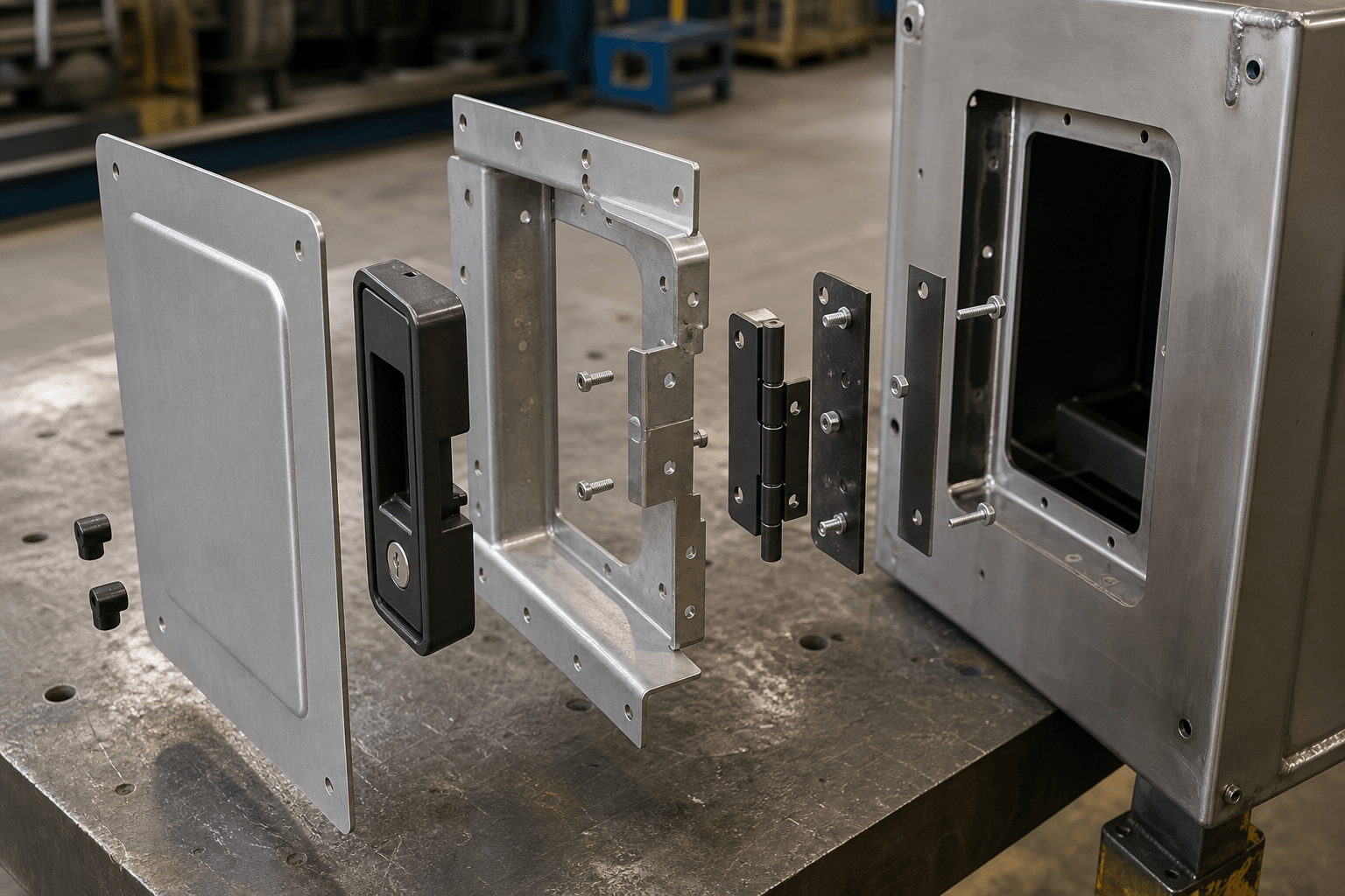
A mechanical sub-assembly is a group of mechanically joined parts prepared away from the final assembly line and delivered as an identifiable integration unit. It is a deliberately chosen BOM and production boundary—not merely any group of attached parts. Its value depends on line balance, interface control, configuration, logistics, serviceability, and total cost.
For example, an OEM may decide whether final-line operators should install an access panel, reinforcement brackets, hinge, handle, and fasteners separately or receive a completed access-door module. This choice affects drawings, sourcing responsibility, finish sequence, inspection, packaging, inventory, and final integration. The OEM should define the boundary through the BOM, drawings, responsibility matrix, and acceptance criteria.
What Defines a Mechanical Sub-Assembly?
The definition becomes commercially important when engineering expects a completed module but purchasing requests prices for fabricated parts. If the documents leave the boundary unclear, suppliers may quote different combinations of joining, hardware, finishing, inspection, and packaging. A useful hierarchy is component → mechanical sub-assembly → higher-level assembly → finished product.
- Individual fabricated part: A cut and bent bracket or panel can remain one BOM item even when several fabrication operations produce it.
- Loose parts kit: Components arrive together but remain unjoined. Kitting changes material presentation without creating a sub-assembly.
- Mechanical sub-assembly: Panels, brackets, frames, enclosure sections, doors, supports, hinges, formed components, and purchased hardware form a defined mechanical module.
- Electrical assembly: Wiring, circuit boards, switches, electrical connections, and electrical tests remain outside the mechanical scope unless project documents assign them.
- Finished product: The completed equipment after all required mechanical, electrical, fluid, software, and other integration.
An OEM may release a welded frame as one fabricated assembly part or control it as a mechanical sub-assembly. Welding alone does not determine its BOM status. Release, inspection, handling, integration, and service responsibilities define the practical boundary. The assembly service scope provides related project context.
When a Separate Module Helps—and When It Does Not
The operational question is whether moving work away from the main line removes a real constraint without creating a larger handling, inventory, or change-control problem. A separate module can support dedicated fixtures or parallel work. It can also consume packaging space, increase work-in-process, or expose completed modules to engineering changes.
| Production condition | Reason to consider a sub-assembly | Reason to retain final-line installation |
|---|---|---|
| Crowded final stations or takt pressure | A separate station can perform repeatable alignment and fastening | The transfer offers little benefit if substantial adjustment remains |
| Stable component combination | Stable content supports repeatable instructions, fixtures, and material presentation | Frequent changes can make completed modules obsolete |
| High configuration variety | A common module may serve several variants | Variant-specific modules increase SKU and scheduling complexity |
| Critical interface | Inspectors can check accessible dimensions before line release | Fit may depend on the mating product rather than the module alone |
| Large or fragile geometry | Pre-assembly may avoid difficult work at a constrained station | The assembled form may ship poorly or suffer distortion and cosmetic damage |
| Delayed configuration | Production can hold common modules until it knows the final configuration | Finished-goods inventory may fall while module inventory rises |
A door shared across several equipment variants might receive its reinforcement and handle before final integration. If technicians must adjust its hinge against each enclosure opening, final-line hinge setting may provide better alignment control.
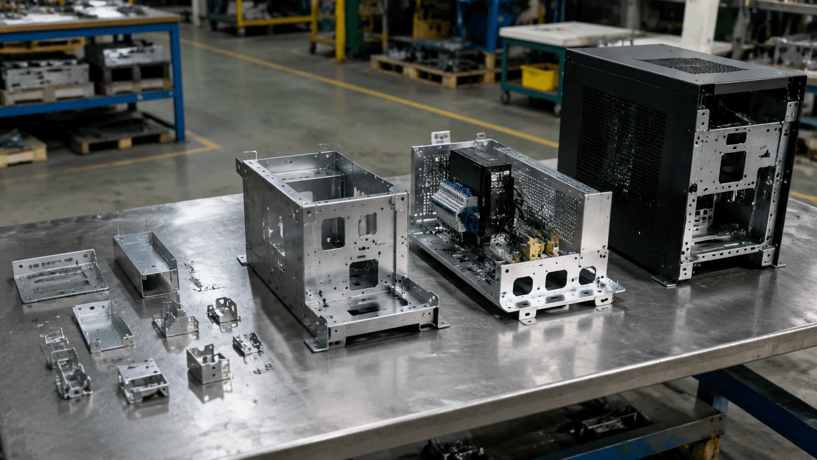
Assembly-Boundary Decision Matrix
When structural parts, configurable hardware, and final-product interfaces appear in the same BOM, the boundary should follow work that teams can complete and accept independently. Stable parts with controllable shared datums are stronger candidates for inclusion. Components that require late configuration, product-level adjustment, or frequent revision usually favor final integration.
| Boundary criterion | Favor inclusion in the module | Favor final integration |
|---|---|---|
| Handling | The unit remains practical to lift, orient, fixture, and install | Assembly creates a bulky, unstable, heavy, or fragile unit |
| Commonality | The combination serves multiple variants | Parts vary by order, destination, or option |
| Datum continuity | Stable module datums control the interfaces | Alignment depends on final-product datums |
| Adjustment | No product-specific setting is needed | Parts require adjustment against the mating equipment |
| Inspection or test access | Critical features remain accessible | Joining hides features or blocks required access |
| Serviceability | Service teams replace the module as one unit | Individual parts require routine replacement |
| Logistics | Packaging can protect the unit efficiently | Loose parts pack more safely or densely |
| Change frequency | Design and approved sources are stable | Revisions or substitutions are frequent |
Also distinguish permanent structure from removable content. A welded frame may provide structural continuity, while a threaded panel or hinge remains removable for alignment or service. For purchased and buyer-supplied components, assign responsibility for sourcing, receipt inspection, storage, ownership, shortages, substitutions, installation, specified tests, packaging, and nonconformance disposition. A design support review can help resolve unclear interfaces or process ownership.
Manufacturing Route and Assembly Sequence
After defining the boundary, process planning must prevent one operation from damaging or obstructing another. The wrong sequence can conceal an inspection feature, block fastening-tool access, coat a functional interface, or force cosmetic rework after assembly.
Sheet material → laser cutting or CNC punching → deburring → bending → specified welding or mechanical joining → surface preparation and finishing
Purchased or buyer-supplied parts → receipt verification → controlled storage
Finished fabricated parts plus approved components → hardware installation → mechanical assembly → inspection → protected packaging → shipment → OEM final integration
This route is illustrative. Drawings, materials, geometry, volume, finish, and acceptance requirements determine the actual sequence. Custom sheet metal fabrication produces the panels, brackets, frames, and enclosure sections. Welding or another specified process joins parts, finishing treats surfaces, assembly integrates components, and inspection checks the agreed requirements.
A machined pin, spacer, shaft, or block remains a separately manufactured BOM item even when workers install it in sheet metal. Turning or milling that component is not a sheet metal fabrication operation.
How Joining Changes the Route
- Welding: Creates permanent joints but introduces heat that can affect geometry or appearance. The plan may need to address sequence, restraint, access, and post-weld checks.
- Riveting: Avoids welding heat and may suit certain thin or dissimilar materials. The design must preserve tool access and allow inspection of the specified installation condition. Removal generally destroys the rivet.
- Threaded fastening: Supports adjustment, disassembly, and service. The design must address tool clearance, retention, tightening requirements, and missing or incorrect hardware.
- Press-fit hardware: Can create captive mounting features when material, thickness, hole preparation, edge distance, installation direction, and finish sequence are suitable.
- Other mechanical joints: Tabs, slots, pins, hinges, or approved clinched features require drawing-defined design and inspection criteria.
Production commonly joins welded structures before powder coating, but the drawing and finish specification govern the route. Threads, grounding points, and contact surfaces may require masking. Coating buildup can interfere with locating holes or mating edges. Installing hardware after coating may protect it from contamination, but installation can scratch cosmetic surfaces. The process plan should therefore define handling protection and repair limits.
Production Validation and Revision Control
The main production risk is not simply whether the module matches its fixture. The module must match the current drawing and integrate with the mating product. A fixture can repeatedly reproduce its own error, so controls should reference functional datums and interfaces rather than fixture dimensions alone.
- Confirm inputs: Verify current drawing and BOM revisions, approved components, work instructions, acceptance criteria, and packaging requirements.
- Control incoming items: Inspect purchased or buyer-supplied parts according to project risk. Segregate damaged items, shortages, and unapproved substitutions.
- Validate fixtures and gauges: Relate locating points to drawing datums and, where necessary, the mating product.
- Use in-process checks: Check relevant formed dimensions, welded geometry, hardware location, joint completion, and finish before later operations hide them.
- Approve the initial build: Use an approved sample, first article, or pilot build where appropriate. Each project should define its approval method.
- Complete final inspection: Check agreed characteristics such as mounting-hole position, interface dimensions, squareness, hinge alignment, gap and flushness, and fastener presence.
Project risk may justify traceability by batch, revision, operator, component lot, or inspection record. An engineering change should trigger revision receipt, inventory segregation, work-instruction updates, fixture review, an implementation date, and confirmation of the first changed batch. Teams must contain nonconforming material. Rework, deviations, use-as-is decisions, and substitutions require authorization. Review the available quality control information when evaluating these controls.
Make-or-Buy Total-Cost Worksheet
A comparison is not valid when the internal estimate covers only assembly labor but the supplier price includes fabrication, components, inspection, and packaging. Define an identical scope for both routes. Separate one-time costs from recurring costs, then test the result against changes in demand, product mix, and forecast. Neither route is inherently cheaper or safer.
Total cost = fabricated parts and purchased components + direct labor + equipment and tooling + fixture maintenance + training and floor space + quality losses and rework + packaging and freight + duties where applicable + inventory carrying cost + administration and supplier management + disruption exposure.
| Option | One-time inputs | Recurring inputs |
|---|---|---|
| Internal assembly | Equipment, fixtures, workstation setup, instructions, training | Labor, space, maintenance, inspection, rework, supervision, handling |
| Purchased module | Supplier review, project transfer, agreed development or fixture charges | Module price, packaging, freight, duties, incoming inspection, administration |
| Inventory and exposure | Transition stock or initial safety-stock setup | Carrying cost, obsolescence, damage, shortages, revision mismatch, interruption |
Run sensitivity checks for annual demand, batch size, product mix, labor rate, shipping volume, forecast volatility, fixture life, and supported scrap or rework assumptions. For break-even analysis, express each route as one-time cost + annual volume × recurring unit cost. Add separately evaluated inventory and risk costs, then solve with buyer-supplied values.
Outsourcing can introduce transport damage, minimum-order constraints, communication delay, intellectual-property exposure, revision mismatch, supply interruption, and excess module inventory. Internal assembly can require underused equipment, floor space, training, supervision, and continuing process ownership. The preferred route is the one that best fits the OEM’s operational, quality, logistics, and risk constraints.
Frequently Asked Questions
What hole alignment details should buyers define before requesting a quote?
Buyers should define the functional requirement, drawing notes, critical dimensions, material or process expectations, and any inspection points related to hole alignment. This helps suppliers quote the same manufacturing scope instead of making different assumptions.
How can tolerance stack affect cost, fit, or lead time?
tolerance stack can change tooling, forming, welding, finishing, inspection, or rework requirements. If buyers do not clarify it early, two supplier quotes may look comparable while covering different production risks.
Why should mating parts be reviewed before prototype approval?
mating parts may look acceptable on a single sample but become harder to control during batch production. Buyers should confirm whether the prototype reflects the same process, finish, and inspection conditions expected for production.
What inspection points matter most for mechanical sub-assembly projects?
Important inspection points usually include fit-critical dimensions, holes or mating areas, cosmetic surfaces, finish build-up, welded or formed features, and any dimensions that affect downstream assembly. These points should appear in the RFQ or drawing notes.
How can buyers reduce fit-up inspection risk before batch production?
Buyers can reduce risk by clarifying drawings, locking key material and finish assumptions, defining inspection timing, approving a representative sample, and confirming which dimensions or surfaces require tighter process control.
How can Yishang help review mechanical sub-assembly requirements?
Yishang can review drawings, RFQ notes, material requirements, tolerance expectations, finish details, samples, and assembly needs to identify unclear assumptions before quoting or batch production.