
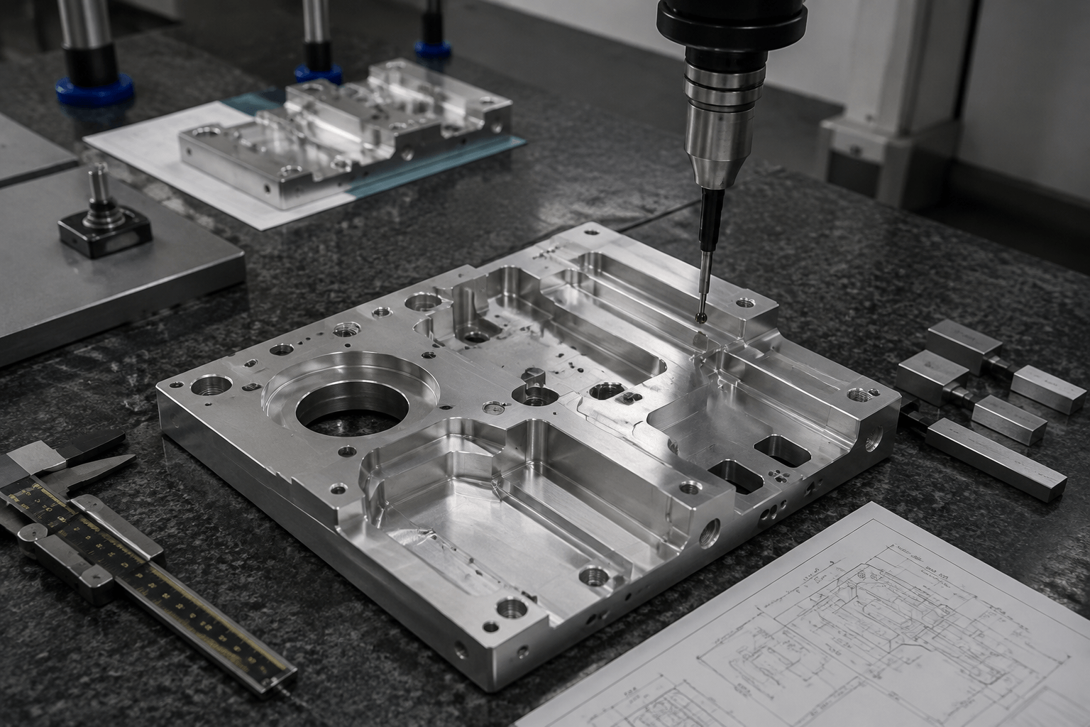
An aluminum CNC service removes material from aluminum billet, plate, bar, or other suitable stock with programmed cutting tools. Milling is used for prismatic or three-dimensional parts, while turning is used for primarily rotational parts; whether the route fits depends on geometry, alloy and temper, stock form, tolerances, finish, quantity, and inspection requirements—not on the word aluminum alone.
An overseas OEM buyer may be comparing a flat cover, constant-profile rail, and pocketed mounting body even though all three are aluminum. Those parts can require different routes, so a CAD file alone does not establish a comparable price. Stock material, workholding, critical dimensions, finish, inspection, packaging, and downstream assembly can all change the manufacturing plan. For an overview of the route, see custom aluminum CNC machining service.
What an aluminum CNC service covers—and when it fits
When a drawing contains pockets, slots, threads, controlled interfaces, or contoured surfaces, the supplier must match the geometry to stock size and a workholding plan before machining can begin. Milling removes material from one or more faces to create those features, while turning rotates bar or similar stock against cutting tools to produce shafts, bores, shoulders, and other rotational features. A part may need one operation or several setups, but neither route should be treated as interchangeable with cutting and forming sheet.
| Route | Typical fit | Important boundary |
|---|---|---|
| CNC milling or turning | Defined 3D features, machined faces, interfaces, or rotational parts. | Tool access, setups, stock removal, workholding, and inspection determine feasibility. |
| Laser cutting, CNC punching, and bending | Mostly flat profiles, openings, and formed sheet-metal parts. | These operations do not automatically replace deep pockets, integral bosses, threads, or complex 3D surfaces. |
| Aluminum extrusion | Long components built around a repeated constant cross-sectional profile. | Profile tooling and any secondary cutting or machining must be evaluated. |
| Die casting | Suitable high-volume housings or structural shapes where tooling economics support a near-net-shape route. | Tooling, draft, alloy, production volume, and finishing requirements can change the decision. |
A flat cover or bent bracket may be better suited to sheet-metal fabrication for flat and formed parts. A pocketed mounting body, controlled interface, or rotational component normally needs a machining review. For a constant-profile component, compare the design with aluminum extrusion as an alternative before committing to extensive stock removal.
Choose the alloy, temper, and stock form together
At RFQ stage, writing only aluminum leaves too many production decisions open. The alloy grade identifies the composition family, the temper identifies its heat-treatment or work-hardening condition, and the stock form determines whether the material is supplied as sheet, plate, bar, or another form. These requirements should be specified separately because they affect strength assumptions, machinability, availability, finishing, documentation, and the implications of later welding.
| Application priority | Possible starting point | Confirm before ordering |
|---|---|---|
| Balanced general machined part | 6061-T6 is often reviewed when machinability, strength, corrosion behavior, availability, and finishing need a practical balance. | Required load, service environment, stock size and form, finish appearance, and material documentation. |
| Higher structural load or weight constraint | 7075-T6 may be considered when the selected section needs higher strength and the design can accept the associated trade-offs. | Corrosion exposure, downstream welding, stock availability, finish requirements, and potentially higher material cost. |
| Structural application and regional stock | 6082-T6 can be appropriate when the required plate, bar, or section is available and matches the part’s structural duty. | Regional supply, load, corrosion environment, machining plan, finish, and certificate requirements. |
| Sheet-oriented forming requirement | 5052 is commonly reviewed for sheet-based designs where forming and the service environment matter. | Do not transfer a 5052 sheet specification automatically to a pocketed billet or bar part; confirm stock form and machinability. |
Selection should connect to the actual load, temperature, corrosive media, weight limit, appearance, electrical requirement, assembly method, and supply route. An alloy that is easy to source in sheet may be unavailable or uneconomic in the plate or bar size needed for CNC machining. The required finish can also influence the decision because alloy, temper, batch, masking, color, and dimensional allowances may affect a post-machining treatment. Availability and any subcontracted finishing should be confirmed rather than assumed.
If the machined part will later be welded, review the material choice before release. Heat-affected zones can change the local properties of some aluminum alloys and tempers, so the original T6 condition should not automatically be assumed to remain unchanged at the joint. This is a material-selection and integration issue, not a reason to treat welding as part of every aluminum CNC service.
Design for cutter access, workholding, and inspection
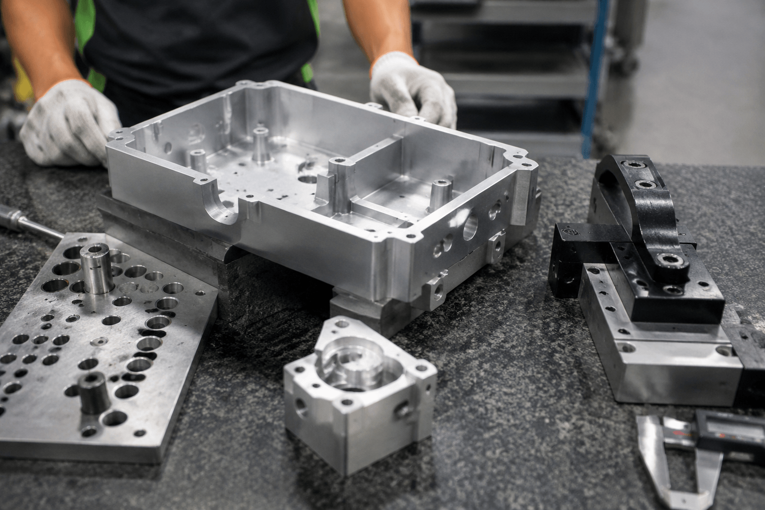
Once the process route and stock are understood, the drawing should be checked for cutter access and stable locating surfaces. Send a 3D CAD model together with a 2D manufacturing drawing: the model conveys the geometry, while the drawing should identify the revision, material, datums, critical dimensions, tolerances, threads, finish, and acceptance requirements.
- Tool access and orientation: Check whether cutters can reach every required face. Deep pockets, enclosed features, undercuts, and long tools may require special tooling or additional setups.
- Internal corner radii: A standard cutter leaves a radius. Sharp internal corners may require smaller tooling, slower machining, or a design change, so add a functional radius where the design permits.
- Walls and cavities: Thin walls, narrow ribs, deep cavities, and long unsupported features can deflect or distort under cutting and clamping forces. Add support or revise the geometry where function allows.
- Holes: State diameter, depth, location tolerance, through or blind condition, chamfers, and any special acceptance requirement. The supplier may choose drilling or interpolation based on the feature and its tolerance.
- Threads: Identify thread size, pitch, depth, blind or through condition, entry treatment, and whether a functional gauge or another acceptance method is required.
- Datums and tolerance allocation: Build the datum scheme around functional interfaces. Reserve tighter control for dimensions that affect fit or performance instead of applying unnecessarily tight tolerances everywhere.
- Burrs and edges: Call out edge breaks, deburring, sharp-edge restrictions, and surfaces that must remain free of tool marks or handling damage.
- Surface finish and fixturing: Identify functional, cosmetic, and masked zones separately. State the required appearance or roughness criterion and consider where the part can be clamped during each setup.
| Design risk | Practical mitigation |
|---|---|
| Deep pocket or undercut | Open the feature, add a radius, reduce depth, or accept an additional setup after supplier review. |
| Thin wall or unsupported rib | Add support or thickness where possible and agree the machining and clamping sequence. |
| Several setups or datum transfers | Align functional datums with accessible locating surfaces and ask the supplier to review the setup plan. |
| Tight tolerances across many features | Reserve tight control for functional interfaces and define the inspection datum clearly. |
There is no universal minimum wall, hole, depth, tolerance, or machining envelope that applies to every supplier. Limits depend on the machines, tooling, material stock, geometry, workholding, and inspection method, so a drawing review should precede a firm commitment.
Agree acceptance requirements before production
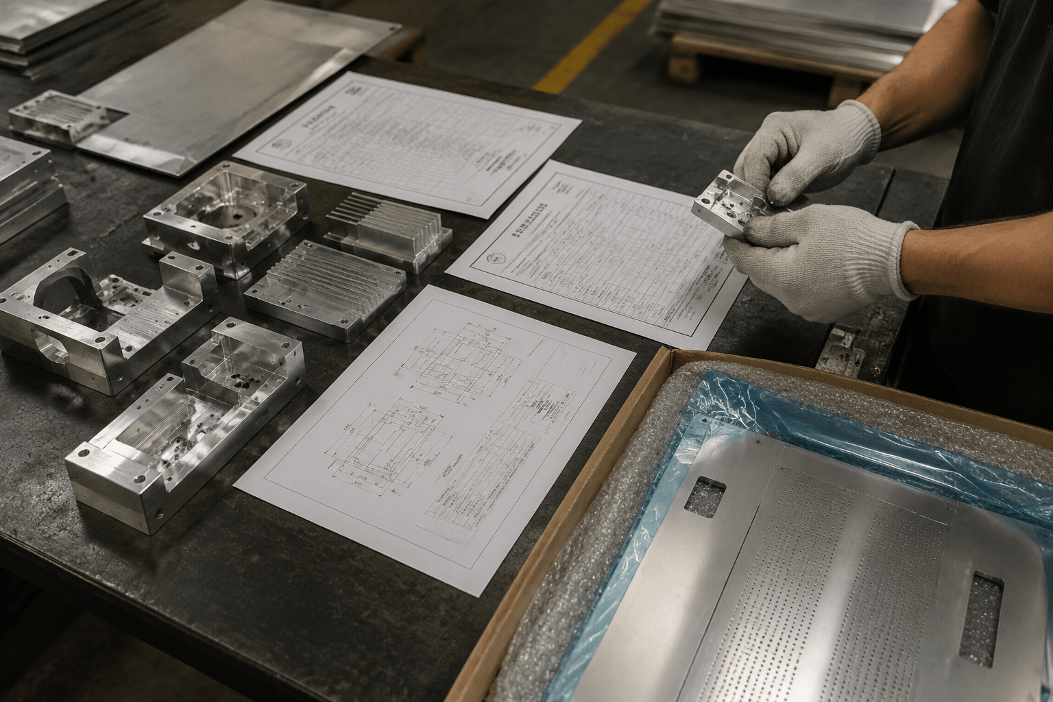
Before the first sample is released, define more than dimensional acceptance. Material identity, threads, surface condition, visual zones, traceability, and export packaging should be agreed with the supplier so the delivered parts can be evaluated against the same requirements.
| Requirement | What the buyer should define | Evidence to discuss |
|---|---|---|
| Material | Exact alloy, temper, stock condition, lot identification, and whether a material certificate is required. | Certificate or other agreed material-grade and temper verification. |
| Dimensions and datums | Critical dimensions, interfaces, hole positions, datum structure, and tolerance requirements. | Critical-dimension report using calibrated measurement; CMM inspection when appropriate and available. |
| Threads | Thread form, size, pitch, depth, entry condition, and functional acceptance method. | Thread inspection or agreed gauge-based evidence. |
| First article | Whether first-article inspection is required and which features it covers. | First-article report by agreement before repeat production. |
| Finish | Roughness or appearance criterion, masking, color, cosmetic surfaces, and dimensional concerns after treatment. | Agreed finish scope and inspection method; availability and subcontracting should be confirmed. |
| Visual condition | Burr removal, edge breaks, tool marks, contamination, and acceptable cosmetic zones. | Visual acceptance criteria linked to the drawing or purchase documents. |
| Traceability and packaging | Part revision, lot labels, separators, scratch protection, and destination-specific packing needs. | Labeling and protective packaging controls for overseas shipment. |
Ask for the inspection plan before production rather than assuming that a CAD file defines the measurement method. Yishang’s quality control and inspection framework provides broader context, while part-specific reports and acceptance criteria still need agreement for each project.
What drives an aluminum CNC quote
If two suppliers quote the same CAD file differently, the difference may come from their assumptions about stock, setup, finishing, documentation, quantity, and delivery scope. The quote should therefore be read as a process plan as well as a unit price.
| Cost driver | Effect on the quotation or delivery plan |
|---|---|
| Material and utilization | Alloy price, stock size, material utilization, and remnant use affect material cost. |
| Programming and setup | Each orientation, datum transfer, and setup adds planning and handling work. |
| Fixture or special workholding | Complex or delicate geometry may need dedicated support or an agreed fixture approach. |
| Machining time and tooling | Deep cavities, difficult access, heavy stock removal, and frequent tool changes can extend processing. |
| Tolerance and inspection | Tighter control and more documented features increase measurement and process-management effort. |
| Finishing | Anodizing, polishing, masking, or another treatment adds scope; availability and subcontracting should be confirmed. |
| Quantity and demand | Prototype setup costs are distributed differently from repeat-production quantities and annual demand. |
| Packaging and shipping | Protective packing, labels, destination, and shipment basis affect the delivered quotation and schedule. |
For samples, the supplier may need to recover programming, setup, and fixture work over a small quantity. In repeat production, an approved process and fixture may distribute those costs more efficiently, but inspection and packaging requirements can still change the unit price. Ask each supplier to state the quantity basis, quote validity period, included finish and documents, packaging basis, shipping scope, and the event that starts the proposed lead-time plan. A CAD file alone cannot fix the price, inspection method, or delivery date.
Build an RFQ package suppliers can price consistently
A technically comparable inquiry gives every supplier the same manufacturing assumptions. It also lets the supplier identify a design risk before commercial commitment instead of pricing an incomplete interpretation of the part.
Aluminum CNC RFQ brief: inputs that control fit, price, quality, and delivery
| Buyer input | Decision it controls |
|---|---|
| 3D CAD model and 2D drawing | Geometry, drawing authority, dimensions, datums, and acceptance basis. |
| Units, revision, and part identification | Prevents quotation against an obsolete or ambiguous file. |
| Alloy, temper, stock form, applicable material standard, and material documents | Controls sourcing, machining behavior, strength assumptions, and traceability. |
| Project stage and quantities | Separates prototype quantity, production quantity, and expected annual or repeat demand. |
| Critical tolerances and interfaces | Defines process difficulty, datum strategy, and inspection scope. |
| Holes, threads, finish, and cosmetic zones | Sets tooling, post-processing, masking, appearance, and acceptance requirements. |
| Inspection reports, first article, and certificates | Clarifies the quality evidence required with the shipment. |
| Packaging, destination, and shipping basis | Exposes export-protection and delivery-scope requirements. |
| Assembly or later welding | Flags integration constraints and material-selection risks before production. |
If an input is not yet fixed, label it as open for DFM review rather than leaving it implicit. The drawing should identify functional datums, critical interfaces, cosmetic surfaces, acceptance criteria, and any feature that could be relaxed after review. Include units, revision status, and part identification even when the CAD model appears unambiguous.
Ask the supplier to return a manufacturability review, material confirmation, process and setup assumptions, fixture assumptions, inspection scope, finish scope, packaging basis, and proposed sample and production schedule. This response makes it easier for engineering and procurement to compare quotations on the same technical basis.
Yishang supports B2B OEM and ODM custom manufacturing projects and has more than 26 years of experience producing custom sheet metal parts and other metal products. It exports to more than 50 countries and holds ISO and RoHS certifications. For a project-specific review, send the 3D CAD model and manufacturing drawing, alloy and temper, stock-form preference, sample and production quantities, critical tolerances, datums, threads, finish, inspection documents, packaging, destination, and any downstream assembly or welding requirement. The review can clarify process assumptions and quotation scope before commercial commitment.
Frequently Asked Questions
These questions address the process, material, and documentation decisions that commonly affect an aluminum CNC RFQ. Final suitability still depends on the part drawing, stock requirements, quantity, and agreed acceptance criteria.
How is aluminum CNC machining different from laser cutting, CNC punching, or sheet-metal fabrication?
CNC machining removes material to create controlled three-dimensional or rotational geometry. Laser cutting and punching mainly create two-dimensional sheet profiles and openings, while bending forms those profiles. A sheet route is not automatically interchangeable with a pocketed, threaded, or precision-interface part.
Should a machined aluminum part use 6061-T6, 7075-T6, 6082-T6, 5052, or another alloy and temper?
Start with the actual load, environment, stock form, finish, availability, cost, and any later welding. 6061-T6 is a common general-purpose reference; 7075-T6 may suit higher-load designs; 6082-T6 may fit certain structural stock requirements; 5052 is primarily a sheet-oriented selection. Confirm the complete specification with the supplier.
Can an aluminum CNC part be welded after machining?
It may be possible, but the alloy and temper must be reviewed first. Welding can change properties in the weld and heat-affected zones, so the strength assumption for an unwelded T6 part may not apply after integration. Tell the supplier about welding at the RFQ stage.
What tolerance, surface-finish, material-certificate, and inspection information belongs in an aluminum CNC RFQ?
Include functional datums, critical dimensions, position and fit requirements, thread details, finish or roughness criteria, masking and cosmetic zones, alloy and temper, certificate needs, critical-dimension reports, first-article requirements, traceability, and packaging acceptance.
When should a buyer consider aluminum extrusion or die casting instead of CNC machining?
Consider extrusion when the component repeats a constant cross-sectional profile and consider die casting when volume and tooling economics support a near-net-shape part. CNC machining remains relevant when the geometry, interfaces, quantity, or expected design changes do not justify profile or casting tooling.
Next step: For an overseas OEM or ODM inquiry, send the current 3D CAD model and 2D drawing together with alloy, temper, stock form, prototype and production quantities, critical datums and tolerances, threads, finish, inspection, packaging, destination, and any downstream assembly or welding requirements. Request a part-specific manufacturability and quotation review so process assumptions are clear before commercial commitment.