
What Is a Lathe?
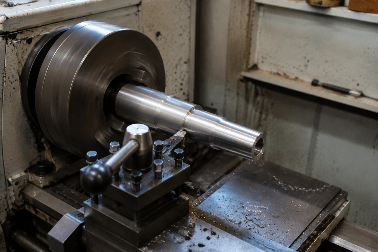
A lathe is a machine tool that holds and rotates a workpiece around a central axis. While the workpiece rotates, a controlled cutting tool removes material and normally feeds along one or more axes.
For example, if a cylindrical shaft must be reduced to a smaller outside diameter, the lathe rotates the shaft while the cutting tool travels along its length. This produces a round surface centered on the axis of rotation. In short, the common search phrase “lathe def” refers to both the machine and this decisive motion: the workpiece rotates while the tool cuts.
A lathe can be manually operated or CNC-controlled. It is most closely associated with turning, the machining process used to create outside diameters, faces, bores, grooves, tapers, threads, and other features organized around a rotating axis.
How Does a Lathe Hold, Rotate, and Cut a Workpiece?
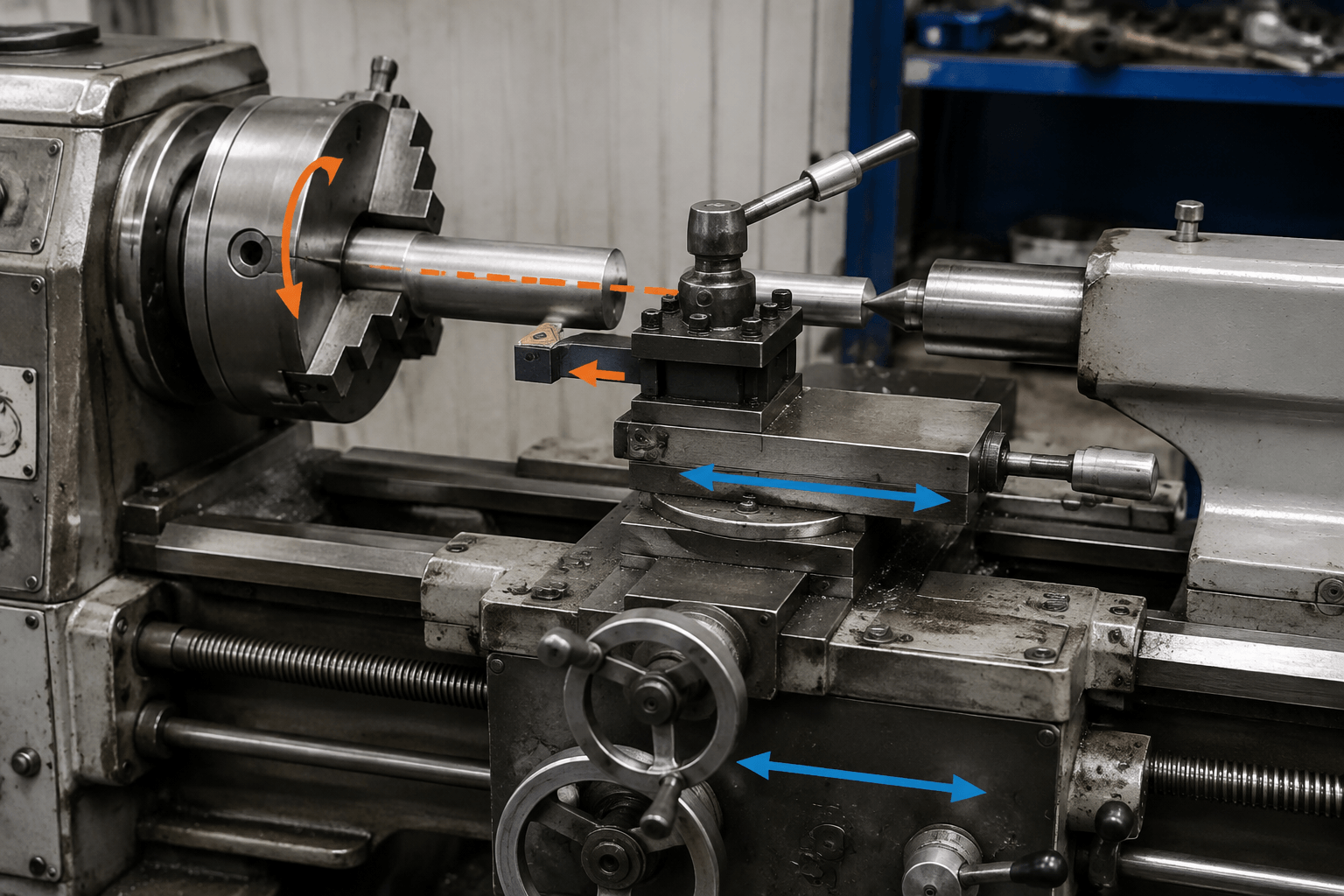
The spindle supplies the rotary motion. A chuck, collet, faceplate, center arrangement, or dedicated fixture connects the workpiece to that spindle. The cutting tool is supported by a carriage or tool slide, which positions and feeds the tool relative to the rotating material.
Rotation: ↻ around the workpiece centerline
[Spindle] — [Chuck or collet] — ===== Rotating workpiece ===== — [Optional tailstock]
▲ Cutting tool
Axial feed: tool moves parallel to the workpiece axis ↔
Radial feed: tool moves toward or away from the axis ↕
──────────────── Carriage or tool slide on the machine bed ────────────────
Roles of the Main Elements
- Spindle: Rotates the workholding device and workpiece. Its centerline establishes the principal axis for the turned geometry.
- Workholding device: A chuck, collet, center, faceplate, or fixture grips and locates the component. The appropriate method depends on the part shape, available gripping area, material, and operation.
- Cutting tool: Engages the material and removes chips. Tool shape and material are selected according to the workpiece material and required operation.
- Carriage or tool slide: Supports the tool and controls its axial and radial position. The cutting tool does not always remain stationary; it normally feeds while the workpiece rotates.
- Bed: Provides the structural base and aligned guideways for the major machine elements.
- Optional tailstock: Can support the free end of a longer workpiece or hold an axial tool, depending on the setup. Not every lathe or turning cycle uses one.
Axial movement is parallel to the spindle centerline, while radial or cross movement is perpendicular to it. Combining these controlled movements with workpiece rotation determines the resulting profile. Secure workholding and alignment matter because they influence whether related diameters, bores, faces, and other features remain correctly positioned around the intended axis.
What Shapes and Features Can a Lathe Produce?
Rotational symmetry is the clearest indication that a part may be suitable for turning. Shafts, pins, bushings, sleeves, rings, and similar forms often contain features that share a common axis, although cylindrical appearance alone does not prove that turning is the best or only process.
| Feature or operation | Typical tool motion | Result |
|---|---|---|
| External turning | The tool feeds mainly along the rotating workpiece. | Creates or reduces an outside diameter and can form shoulders between different diameters. |
| Facing | The tool feeds radially across an end. | Creates a flat end face perpendicular to the rotational axis. |
| Boring | A boring tool feeds inside an existing opening. | Enlarges or finishes an internal cylindrical surface. |
| Grooving | A narrow tool feeds radially or follows a defined profile. | Produces an internal or external recess around the axis. |
| Taper turning | Axial and radial positions change together. | Produces a conical surface rather than a constant diameter. |
| Threading | Tool travel is coordinated with workpiece rotation. | Creates an internal or external helical thread. |
A conventional lathe is less naturally suited to features that do not repeat around the rotational axis. Cross-holes, wrench flats, off-center pockets, and complex side features may require a separate milling or drilling operation. A configured turning center may produce some of these features with live tooling, additional axes, or a sub-spindle, but those functions are not present on every machine and do not make every non-round feature economical to turn.
Lathe, Turning, CNC Lathe, and Turning Center
Lathe names the machine category, while turning names the material-removal process based on rotating the workpiece against a cutting tool. The terms are related but not interchangeable: a component can undergo a turning operation, and a lathe is one type of machine used to perform it.
| Term | High-level meaning | Important distinction |
|---|---|---|
| Manual lathe | A lathe on which the operator directly controls setup and tool movement through manual controls or machine feeds. | It demonstrates that a lathe is not automatically a CNC machine. |
| CNC lathe | A lathe whose programmed control coordinates spindle rotation, tool position, and feed movements. | The available axes, tooling, workholding, and automation depend on the machine configuration. |
| Automatic lathe | A lathe designed to automate recurring parts of the machining cycle and, in some configurations, material handling. | The term covers different machine arrangements and does not identify one universal capability. |
| Vertical lathe | A lathe with a principally vertical spindle orientation. | Its orientation can suit workpieces that are more practical to support on a horizontal table, but process fit still depends on the actual geometry and machine capacity. |
| Turning center | A CNC turning machine designed for an integrated range of operations. | Depending on configuration, it may add automatic tool changing, live tooling, a sub-spindle, or additional controlled axes. |
Lathe vs Milling vs Sheet Metal Fabrication: Identify the Process from Part Geometry
The most useful distinction is not simply whether a component contains a hole or a flat surface. It is which motion and starting material most naturally create the dominant geometry.
| Process family | Controlling motion | Strong geometry indicator | Representative component |
|---|---|---|---|
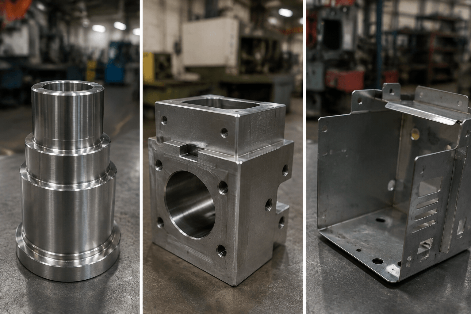
| Lathe turning | The workpiece rotates while a cutting tool feeds. | Most critical surfaces are diameters, bores, faces, grooves, tapers, or threads sharing an axis. | A stepped shaft or cylindrical bushing. |
| Milling | A cutting tool rotates while the workpiece is held and positioned relative to it. | The part is primarily prismatic or contains planes, pockets, slots, angled faces, or off-axis features. | A rectangular block with machined pockets and a bolt pattern. |
| Sheet metal fabrication | Sheet material is cut and may then be formed and joined. | The part is designed around sheet thickness, flat patterns, bends, flanges, and formed walls. | A bent enclosure, panel, or formed bracket. |
Geometry-Based Drawing Examples
Example 1: Stepped shaft. A drawing shows several outside diameters, an end face, a circumferential groove, and an axial threaded section. Because these features share a centerline, turning is a logical primary process candidate.
Example 2: Prismatic mounting block. A solid rectangular component has broad flat faces, a pocket, side slots, and holes arranged on different faces. Milling is usually the more natural primary machining family because rotating the whole workpiece does not directly generate its dominant geometry.
Example 3: Bent enclosure. A component has walls with a consistent sheet thickness, corner bends, mounting flanges, and cut openings. This geometry points toward custom sheet metal fabrication, not toward a lathe as the primary process.
Example 4: Shaft with flats and cross-holes. The diameters and faces may be turned first, while the flats and cross-holes may be produced with live tooling or in a secondary milling or drilling setup. One component can therefore combine turning with other machining processes.
Quick Process-Fit Questions
- Do most functional features share one rotational centerline? If so, investigate turning first.
- Do pockets, planes, slots, or off-axis holes dominate the drawing? Milling may be the better primary process.
- Is the design based on a cut flat pattern and controlled bends? It belongs in the sheet metal fabrication family.
- Does the component combine rotational and non-round geometry? Evaluate a mixed process route rather than forcing the entire part into one category.
Final process selection can also depend on material, overall diameter and length, quantity, required relationships between features, and specified tolerances. These factors should refine a geometry-based decision rather than replace it.
Confirm Whether Your Part Belongs in Turning or Another Process
If a drawing combines turned, milled, and formed-sheet features, Yishang can review the part or assembly and discuss an appropriate custom manufacturing route. Send the part drawing or 3D model, material, expected quantity, and critical dimensions or functional features. For rotational and other solid-stock components, see the CNC machining service context; for panels, brackets, and enclosures, review the sheet metal fabrication option above.
Where RFQ Assumptions Create Cost and Production Risk
Many sheet metal fabrication problems begin before production starts. If drawings, tolerances, finish expectations, material grades, or assembly requirements are unclear, suppliers may quote based on different assumptions. That can make prices difficult to compare and may lead to rework, cosmetic rejection, assembly misalignment, or production delays later.
For OEM buyers, the goal is not simply to request the lowest price. The goal is to make sure each supplier is quoting the same manufacturing reality. Before confirming an order, clarify which dimensions are fit-critical, which surfaces are cosmetic, whether prototypes must match batch-production conditions, and how finished parts will be inspected.
Frequently Asked Questions
What lathe def details should buyers define before requesting a quote?
Buyers should define the functional requirement, drawing notes, critical dimensions, material or process expectations, and any inspection points related to lathe def. This helps suppliers quote the same manufacturing scope instead of making different assumptions.
How can RFQ details affect cost, fit, or lead time?
RFQ details can change tooling, forming, welding, finishing, inspection, or rework requirements. If buyers do not clarify it early, two supplier quotes may look comparable while covering different production risks.
Why should drawing requirements be reviewed before prototype approval?
drawing requirements may look acceptable on a single sample but become harder to control during batch production. Buyers should confirm whether the prototype reflects the same process, finish, and inspection conditions expected for production.
What inspection points matter most for lathe def projects?
Important inspection points usually include fit-critical dimensions, holes or mating areas, cosmetic surfaces, finish build-up, welded or formed features, and any dimensions that affect downstream assembly. These points should appear in the RFQ or drawing notes.
How can buyers reduce prototype approval risk before batch production?
Buyers can reduce risk by clarifying drawings, locking key material and finish assumptions, defining inspection timing, approving a representative sample, and confirming which dimensions or surfaces require tighter process control.
How can Yishang help review lathe def requirements?
Yishang can review drawings, RFQ notes, material requirements, tolerance expectations, finish details, samples, and assembly needs to identify unclear assumptions before quoting or batch production.