
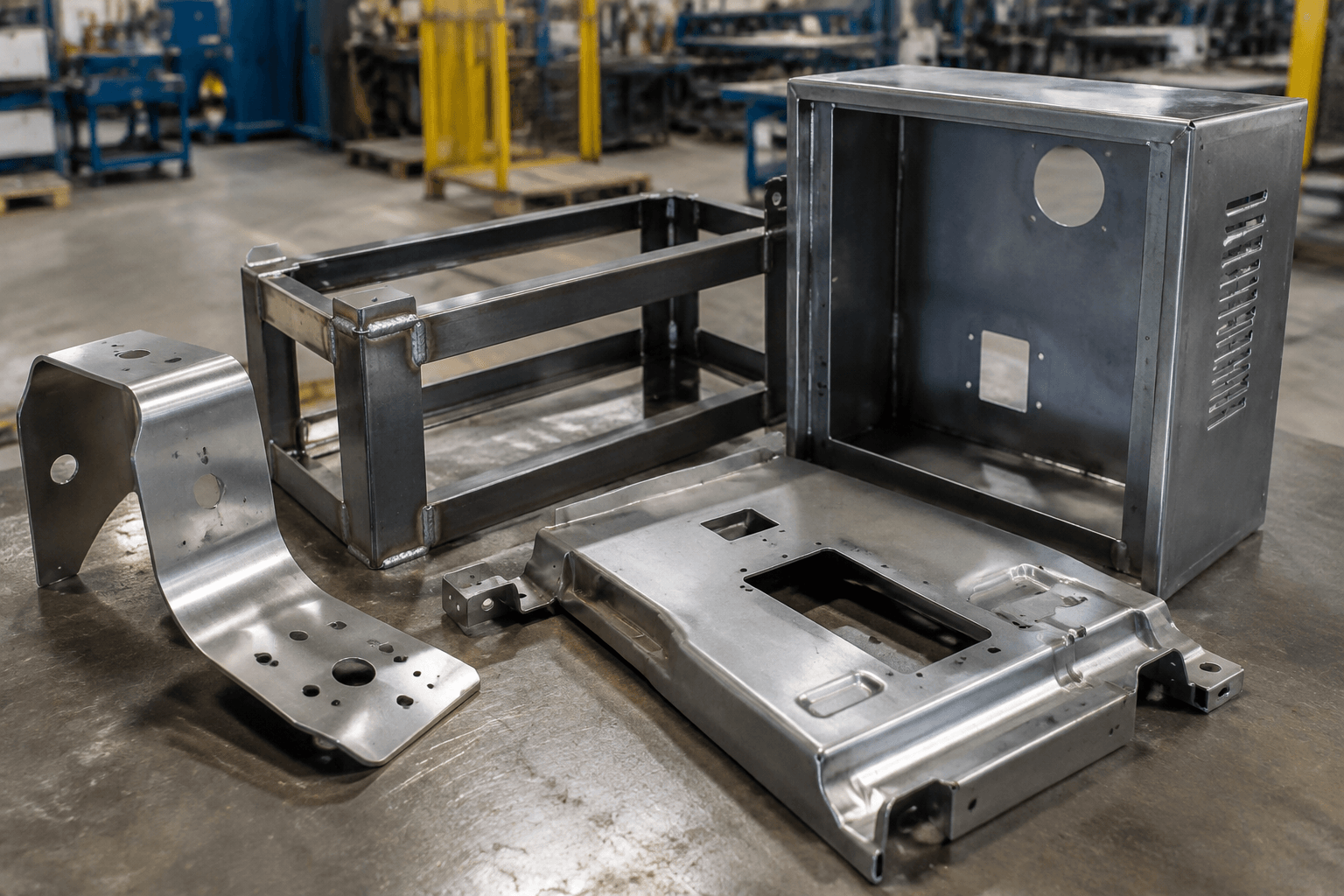
Fabricated components are metal parts or assemblies made from stock sheet, plate, tube, bar, or section through cutting, forming, joining, or a combination of these operations. A single cut-and-formed piece is one component; multiple pieces joined into a functional structure are a fabricated assembly. Unlike casting, fabrication does not pour molten metal into a mold; unlike full CNC machining, it does not primarily remove material from solid stock. Material, geometry, joints, loads, tolerances, quantity, and design-change frequency determine the route.
In short: Fabrication is suitable to investigate when stock-based cutting, forming, and optional joining can meet the required geometry, load, interfaces, tolerances, quantity, and design-change plan.
For sourcing, those requirements must be considered together. No route is automatically stronger, cheaper, faster, or more reliable than casting or machining for every component.
Fabricated components: the practical manufacturing definition
On a new OEM project, fabrication starts with the form of material that can be purchased and handled, not with a mold or a solid block selected for material removal. The supplier converts that stock into the required profile, bends, openings, sections, and joints.
A single fabricated component can pass through cutting and several forming operations while remaining one piece of metal, such as a laser-cut and bent bracket or formed cover. A fabricated assembly contains multiple parts joined into a functional structure, such as a welded frame, cabinet, rack, or support chassis. Welding is one possible joining method; bolts, rivets, clinching, or another specified method may also be used.
Fabrication is therefore a family of manufacturing routes rather than one machine or operation. It is distinct from casting, forging, extrusion, injection molding, and a part machined entirely from solid stock. A fabricated part can still receive secondary machining for a controlled face, hole, or interface.
Common OEM examples and what their features require
Part category helps an OEM identify likely fabrication work, but it does not establish suitability. Functional interfaces, loads, environment, tolerances, and the need for an open structure, protective housing, or multi-piece assembly still control the route.
- Brackets and supports: Cut profiles and bends may create the shape. Hole position, edge distance, bend angle, and load direction affect fit and performance.
- Frames and chassis: Tube, angle, channel, plate, or formed members may be joined into an open structure. Squareness, datums, weld access, and assembly sequence matter.
- Enclosures and cabinets: Panels, bends, doors, openings, fasteners, hinges, and mounting features may need alignment, flatness, sealing surfaces, and a specified finish.
- Display racks and stands: Formed sheet, tube, shelves, and joined subassemblies must be considered together with stability, repeatable fit, appearance, and shipment protection.
- Laser-cut and bent components: A flat pattern can include openings and interfaces before bending creates the three-dimensional form. Tool access and bend sequence affect hole placement.
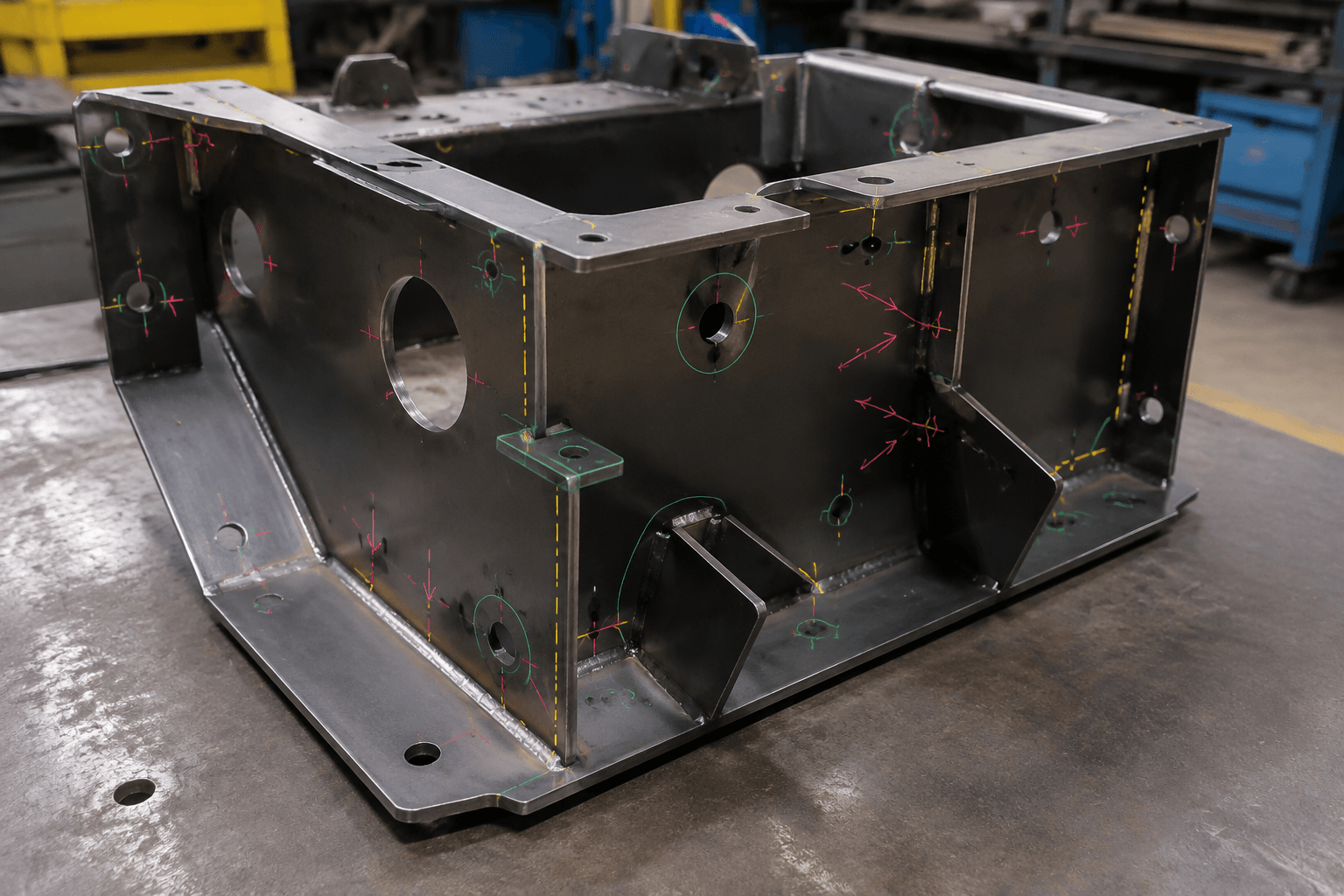
- Welded assemblies: Several cut or formed members can become one structure. Joint access, fit-up, heat-related distortion, residual stress, and inspection access should be addressed.
Illustrative project examples
The following project examples are route-screening illustrations, not customer case studies:
- Bent mounting-bracket project: An OEM drawing may call for a flat pattern, two bends, and mounting holes. Review hole-to-bend relationships, bend sequence, load direction, and whether the mounting face needs machining.
- Cabinet or enclosure project: The design may combine panels, openings, doors, fasteners, and a finish. Check flatness, interfaces, sealing or mounting surfaces, joining access, and packaging protection as one assembly requirement.
- Frame or display-rack project: The design may use tube, plate, shelves, and joined subassemblies. Confirm datums, squareness, fit-up, weld access, stability, load conditions, finish, and shipment protection before choosing the route.
These are application examples, not automatic process recommendations. A bracket may need machining or another route if its interface tolerances or load case require it.
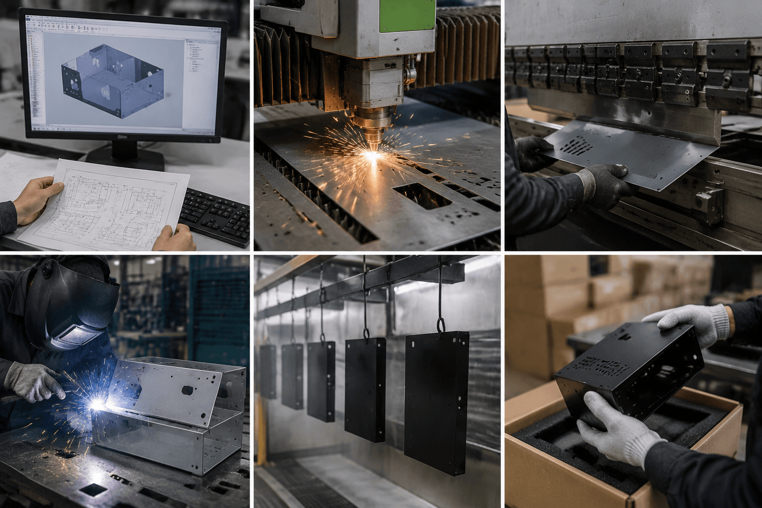
From drawing review to inspected part: the fabrication route
After receiving an OEM drawing or prototype, a supplier should select only the operations the part actually needs. A fabricated component does not automatically require laser cutting, punching, bending, welding, finishing, and assembly.
- Review the drawing or prototype. Check the revision, material, thickness, datums, bend locations, interfaces, and inspection notes. Look for bend conflicts, inaccessible welds, assembly interference, tolerance concerns, and unnecessary operations.
- Choose stock and cut the blanks or members. Sheet, plate, tube, bar, or section must match the approved specification. Laser cutting may suit profiles and openings, while CNC punching may suit repeated holes or selected sheet-metal features when the geometry and production requirements support it.
- Form the required geometry. Bending or another forming operation can create flanges, channels, returns, or curved sections. Bend radius, direction, material orientation, springback, and sequence influence final angles and mating features.
- Join pieces when required. Welding, bolts, rivets, clinching, or another specified method can create the assembly. Joint form, fit-up, access, heat input, appearance, and distortion sensitivity should be defined rather than assumed.
- Apply optional secondary work. Deburring, post-weld machining, reaming, coating, plating, or another finish is used only when the specification requires it. Machining remains a distinct operation even when it follows fabrication.
- Assemble when included in the supply scope. Fasteners, hardware, seals, or subcomponents may be installed when the drawing or purchase requirement calls for a complete assembly.
- Inspect and pack. Inspection may cover visual condition, critical dimensions, datums, fit, finish, weld appearance, material documentation, and any contractually required testing or non-destructive examination. Packing should protect edges, finished surfaces, and assembled features during export handling.
The sequence changes with grade, thickness, geometry, quantity, tolerance, joining method, and final-use conditions. Drawing review should confirm where dimensional variation or weld distortion could affect a functional interface. A stock-based route can be reviewed through custom sheet metal fabrication, but the part drawing—not the process label—sets the actual scope.
Choosing among fabrication, casting, and CNC machining
Compare the routes by starting form, geometry, tooling exposure, quantity, revision frequency, tolerance, load conditions, joining needs, and secondary operations. Complexity by itself is not a sufficient decision rule.
| Decision variable | Fabrication | Casting | CNC machining |
|---|---|---|---|
| Starting form | Sheet, plate, tube, bar, or section is cut and may be formed or joined. | Molten metal fills a mold and solidifies into a near-net shape. | Solid or semi-finished stock is held while material is removed. |
| Geometry and access | Panels, brackets, frames, hollow structures, and accessible multi-piece forms may fit this route. | Integrated contours, ribs, bosses, or internal forms may be possible when mold filling and release are suitable. | Pockets, faces, holes, profiles, and interfaces can be made where cutting tools can reach. |
| Tooling and changes | Programming, forming setup, fixtures, and joint planning are evaluated; a revision may affect several operations. | Molds, patterns, dies, and process development can make design changes consequential. | Programming, workholding, cutting tools, stock, and setups change with the design. |
| Quantity and lifecycle | Expected demand, labor, fixtures, repeatability, and joining effort affect total cost. | Tooling, yield, finishing, machining, demand, and revision frequency interact; no universal volume cutoff applies. | Material removal, setups, cycle content, tooling, and repeatability affect prototype and production economics. |
| Tolerance and surface | Forming and joining can introduce variation or distortion; critical faces or holes may need secondary machining. | As-cast dimensions and surfaces may need finishing or machining for functional features. | Specified machined features can be produced subject to the drawing and process capability. |
| Performance and risk | Assess section design, joint quality, fit-up, incomplete fusion, residual stress, distortion, load direction, vibration, and fatigue. | Assess porosity, shrinkage, inclusions, cold shuts, hot cracks, alloy behavior, and load or fatigue conditions. | Assess parent material, remaining section, machined geometry, surface condition, and stress or fatigue requirements. |
Large panels or structures assembled from accessible members may warrant a fabrication review, while an integrated housing with ribs, bosses, or internal forms may justify investigating a custom die-casting route. The cast design still needs mold access, filling and solidification control, and possible post-machining. A fabricated design needs accessible joints, fixtures, fit-up control, and a plan for distortion.
Casting is not limited to one demand level, and fabrication is not limited to another. Compare stock, labor, tooling, fixtures, machining, inspection, finishing, packaging, repeatability, and the cost of future revisions. Where tight interfaces or deep pockets dominate, CNC machining may be the main route or a secondary operation after fabrication or casting.
Design details that make a fabricated component production-ready
A production-ready specification connects the part’s material and geometry to its load case, joints, functional interfaces, finish, and inspection method.
- Material and environment: State whether the stock is carbon steel, stainless steel, aluminum, or another exact grade, along with thickness or section size and any weight target. Include temperature, moisture, chemicals, outdoor exposure, wear, cleaning, and corrosion conditions.
- Forming geometry: Define bend radii and direction, flatness, bend-sequence constraints, cutout placement, and hole-to-edge or hole-to-bend relationships. Leave practical access for tools, fasteners, and mating parts.
- Joints and machining: Show joint form, weld locations, weld access, appearance requirements, and areas that must remain free of spatter or excessive distortion. Identify any post-weld machining allowance, datum, and finished-surface requirement.
- Loads and tolerances: State whether service includes static load, impact, vibration, wear, or repeated fatigue loading. Mark critical dimensions, datums, flatness, and functional fits separately from non-critical dimensions.
- Finish and inspection: Define appearance, corrosion protection, finish consistency, masking, labeling, and uncoated areas. Agree on first-article or sample approval, dimensional reporting, material documents, visual weld criteria, or non-destructive testing when required. Inspection and process-control expectations can be discussed alongside quality-control information.
What overseas OEM buyers should verify before production
Before releasing a prototype or repeat batch, establish a controlled supplier package that connects the approved design to the fabrication route and acceptance plan.
- Set the document baseline. Provide the revision-controlled 2D drawing, bill of materials, and 3D CAD model when available. Identify whether the order covers one component or a complete assembly.
- State program status. Give the initial quantity, expected repeat or annual demand, and whether the job is a prototype, first article, pilot batch, or repeat production. Record whether the design is frozen.
- Confirm route constraints. Identify which features are cut, formed, joined, machined, finished, assembled, or supplied as-is. If the route is open, ask for documented process assumptions.
- Define acceptance. Mark critical dimensions, datums, interfaces, fit, weld appearance, finish, labeling, packaging, and required documentation. Specify which items belong in a dimensional report.
- Review the first article. Check fit, interference, hole alignment, distortion, assembly sequence, and finish before repeat production.
- Control changes and shipment. Agree how drawing revisions, inspection findings, approved deviations, packaging updates, traceability, and export documentation will be recorded and communicated.
For a technical route review and qualified RFQ, send Yishang the 2D drawing or 3D CAD file, material grade and thickness, initial and expected repeat quantities, critical dimensions and interfaces, load and environment details, joining and finish requirements, inspection, packaging, and documentation needs, plus the prototype or first-article expectation.
Yishang brings more than 26 years of custom metal-manufacturing experience and exports to more than 50 countries. A route review can help determine whether a cut, formed, and joined process fits the component before the buyer commits to a prototype or batch-production plan.
Frequently Asked Questions
What fabricated components details should buyers define before requesting a quote?
Buyers should define the functional requirement, drawing notes, critical dimensions, material or process expectations, and any inspection points related to fabricated components. This helps suppliers quote the same manufacturing scope instead of making different assumptions.
How can RFQ details affect cost, fit, or lead time?
RFQ details can change tooling, forming, welding, finishing, inspection, or rework requirements. If buyers do not clarify it early, two supplier quotes may look comparable while covering different production risks.
Why should drawing requirements be reviewed before prototype approval?
drawing requirements may look acceptable on a single sample but become harder to control during batch production. Buyers should confirm whether the prototype reflects the same process, finish, and inspection conditions expected for production.
What inspection points matter most for fabricated components projects?
Important inspection points usually include fit-critical dimensions, holes or mating areas, cosmetic surfaces, finish build-up, welded or formed features, and any dimensions that affect downstream assembly. These points should appear in the RFQ or drawing notes.
How can buyers reduce prototype approval risk before batch production?
Buyers can reduce risk by clarifying drawings, locking key material and finish assumptions, defining inspection timing, approving a representative sample, and confirming which dimensions or surfaces require tighter process control.
How can Yishang help review fabricated components requirements?
Yishang can review drawings, RFQ notes, material requirements, tolerance expectations, finish details, samples, and assembly needs to identify unclear assumptions before quoting or batch production.