
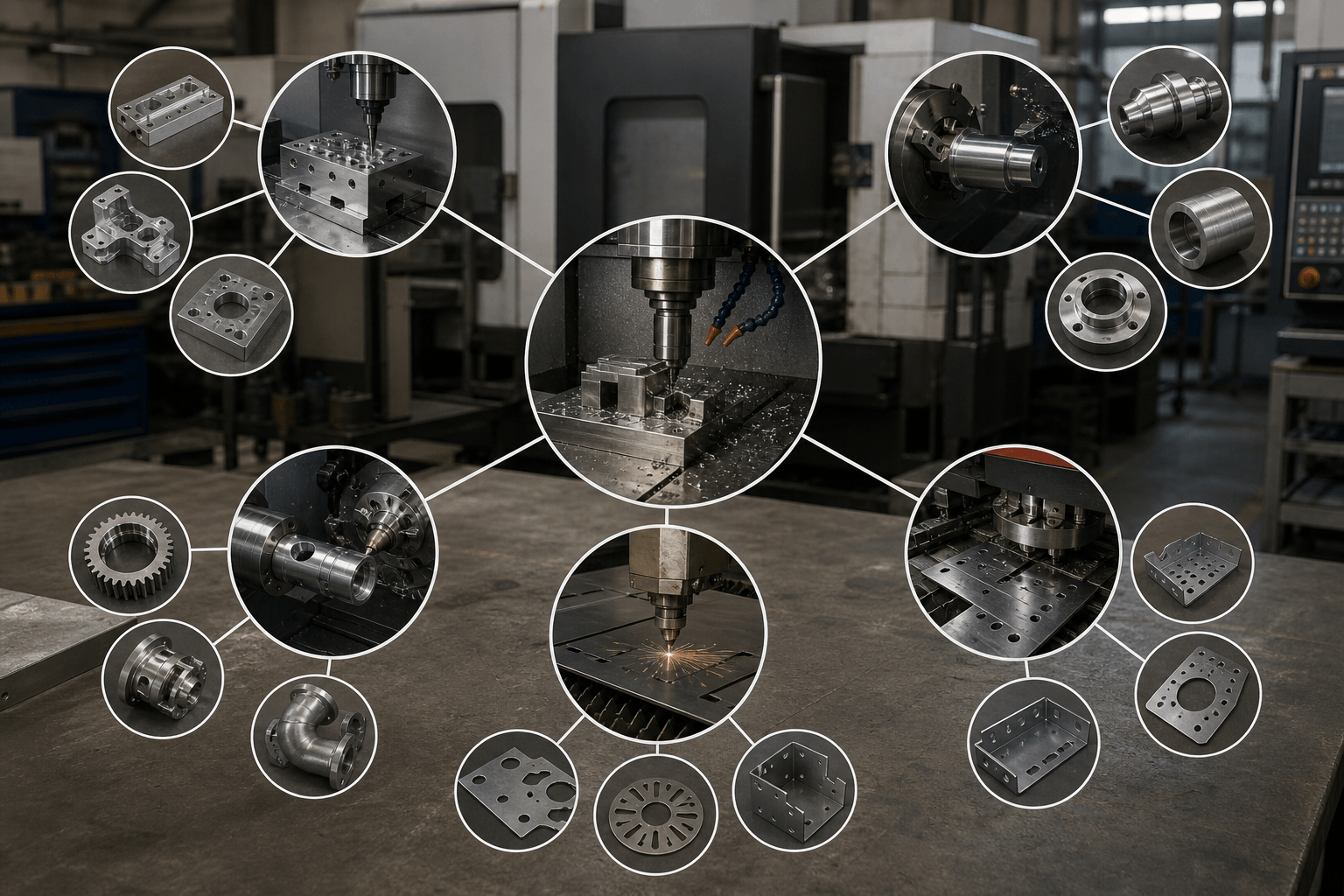
A computer numerical control application uses programmed digital instructions to direct machine movement, cutting, forming, or another manufacturing action. CNC is a control method and umbrella term, not a single machine or an automatic synonym for CNC milling. Milling, turning, laser cutting, and punching are distinct processes, so the appropriate route depends on stock form, geometry, access, material, tolerances, quantity, and inspection requirements.
This distinction matters when an OEM or ODM CAD model is ready for review but the manufacturing route is not fixed. A solid machined component, turned shaft, and sheet-metal enclosure may all use programmed control while requiring different tooling, workholding, programming, inspection, and cost assumptions.
What the CNC Application Term Covers
A CNC application describes how programmed instructions control relevant manufacturing equipment. CAD/CAM data is used to create tool paths and machine instructions, commonly translated into G-code or another machine-specific format. Depending on the equipment, these instructions can control coordinate movement, feed, spindle behavior, cooling, tool changes, or sheet positioning.
The process still determines what the machine does. CNC milling removes material from solid or near-solid stock with rotating cutters. CNC turning produces rotational features around a centerline. CNC laser cutting follows profiles through sheet with a focused beam, while CNC punching uses tooling to create compatible sheet features such as holes, slots, louvers, or knockouts. These are not interchangeable routes for solid-part production; stock form, edge condition, workholding, tolerance, and downstream operations must be reviewed separately.
Process Families by Geometry and Tool Access
Start by classifying the dominant form as prismatic, rotational, complex-surface, or sheet-based. Then evaluate axis count against feature access, datum control, workholding, and setup requirements rather than treating it as a general machine-quality ranking.
| CNC application | Typical geometry | Key consideration |
|---|---|---|
| 3-axis machining | Prismatic faces, pockets, planar surfaces, holes, slots, and accessible cavities | Different sides may require repositioning and a new work coordinate or datum check. |
| 4-axis machining | Indexed faces, radial holes, and features distributed around a component | A rotary axis may improve access or reduce manual repositioning when the fixture and geometry justify it. |
| 5-axis machining | Angled holes, contoured parts, curved surfaces, and multi-face geometry | Tool orientation may improve access, but programming, collision control, workholding, and verification can be more demanding. |
| CNC turning | Shafts, pins, bushings, shoulders, grooves, threads, tapers, and concentric bores | The dominant geometry should be rotational around a defined centerline. |
| Mill-turn | Turned diameters combined with flats, cross-holes, slots, or off-center milled features | Combining operations may reduce handling, but access, tooling, programming, and production economics still need review. |
| CNC laser cutting | Flat sheet profiles, openings, ventilation patterns, and blanks for forming | Grade, thickness, cut edge, heat effects, nesting, and later forming affect suitability. |
| CNC punching | Repeated holes, slots, louvers, knockouts, and other tool-compatible sheet features | Tooling availability, feature spacing, edge distance, distortion, and quantity require checking. |
From Part Feature to CNC Application
| Part feature | Likely route | Question to resolve |
|---|---|---|
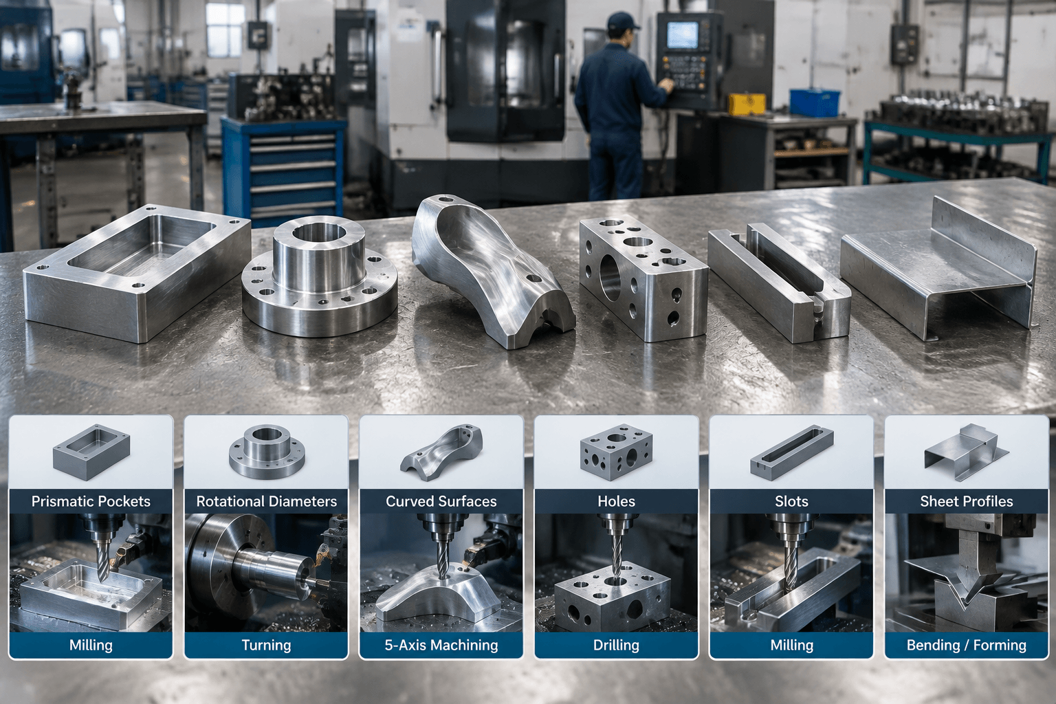
| Pockets and prismatic faces | 3-axis, 4-axis, or 5-axis milling | Can the cutter reach each surface without excessive extension or repositioning? |
| Complex curved or angled surfaces | Often 5-axis, or indexed 3-axis or 4-axis work | Is simultaneous movement necessary, or can indexed setups provide adequate access? |
| Concentric bores and external diameters | CNC turning | Which surfaces must remain concentric, and how will they be held and inspected? |
| Turned diameters with flats or cross-holes | Mill-turn or separate turning and milling | Does fewer handling steps justify added programming or equipment cost? |
| Flat sheet profile | Laser cutting, punching, or another sheet route | What are the thickness, edge, hole, distortion, and forming requirements? |
| Enclosure, bracket, or frame | Sheet-metal cutting and forming, possibly with machined interfaces | Which inserts, assembly features, or allowances affect the sequence? |
For solid-part planning, see CNC machining from first sample to repeat production. Components primarily made by cutting and forming sheet should be evaluated through a custom sheet-metal fabrication route.
Route Selection: Material, Tolerance, Quantity, and Cost
A part can be technically machinable without that being the best production route. Select the process by connecting shape and stock form with material behavior, critical dimensions, surface condition, quantity, and the evidence needed to verify the result.
| Review factor | Effect on route selection |
|---|---|
| Material and stock | Grade, temper or condition, starting dimensions, availability, and machining allowance influence cutting strategy, tool behavior, and material cost. |
| Access and workholding | Orientation, clamping surfaces, tool reach, and datum visibility determine whether features can be produced without distortion or excessive setup changes. |
| Tolerance and surface condition | Tight relationships or specified roughness may require controlled setups, finishing passes, suitable measurement methods, and added inspection. |
| Quantity and design maturity | Prototypes spread programming and setup effort over few parts. Repeat batches may distribute preparation more effectively, while design changes can reset the assumptions. |
| Inspection needs | Critical features, material identification, traceability, measurement method, and batch records can affect process planning and cost. |
Material labels need more precise review. Stainless steel grades can differ in work hardening, heat management, tool wear, and cutting parameters. Aluminum often supports efficient cutting, but alloy or temper, burr formation, thin-wall movement, and distortion still affect feasibility.
- Programming and process planning: Multi-axis paths, simulation, collision checking, datum strategy, and fixture planning can require additional preparation.
- Tooling and workholding: Custom jaws, fixtures, long-reach tools, or special cutters may be needed without obstructing or deforming critical features.
- Machine time: Material removal, tool engagement, operations, repositioning, tool changes, and finishing passes affect the cycle.
- Inspection and records: Measurements, material documentation, and critical-feature reporting add effort when the application requires them.
Additional axes may improve access or reduce repositioning, but they do not automatically provide higher accuracy, lower cost, or shorter production time. A stable 3-axis strategy may suit accessible geometry, while 4-axis, 5-axis, or mill-turn equipment becomes valuable when it solves a real access, datum, or setup problem.
DFM Features That Increase Application Risk
Before quotation or production release, review features that create tool-access, rigidity, datum, or inspection problems.
| Design feature | Risk | Review action |
|---|---|---|
| Deep cavity | Long reach can reduce rigidity and complicate chip evacuation, cooling, visibility, and surface control. | Review depth-to-width relationships, corner access, entry, and whether the cavity can be opened or divided. |
| Thin wall or tall slender feature | Cutting forces and clamping can cause deflection, vibration, or distortion. | Check support, machining sequence, and whether extra stock should remain until finishing. |
| Small internal radius | Small cutters may require more passes and longer cycles while being less rigid. | Use the largest functionally acceptable radius and identify genuinely critical corners. |
| High length-to-diameter ratio | Slender tools or features are more vulnerable to deflection and chatter. | Shorten reach, improve access, add support, or reconsider proportions where function permits. |
| Deep thread or obstructed hole | Tool reach, chip removal, tap clearance, thread milling, and measurement can be difficult. | Specify full thread depth separately from drilled depth and confirm inspection access. |
| Weak datum scheme | Unrelated references can cause setup changes and tolerance accumulation. | Base critical dimensions on functional mounting, alignment, or assembly references. |
| Broad tight-tolerance or finish callouts | Noncritical surfaces may receive unnecessary finishing and inspection. | Apply requirements selectively to fit, sealing, motion, appearance, or assembly interfaces. |
Tolerance stacking also matters when a machined part locates against a formed panel, frame, bearing, seal, or another component. Individual dimensions may be acceptable while their accumulated variation creates an interface problem.
Need help reviewing the manufacturing route? Share the available drawing, CAD model, material grade, quantity, critical interfaces, and inspection priorities. Yishang can discuss whether machining, sheet-metal fabrication, or a combined route is practical before design finalization.
From CAD/CAM Data to a Verified Part
A program alone does not guarantee consistency. Drawing requirements, datum definition, workholding, tooling, machine access, process control, and inspection must support one another. The same model may require a different strategy when material, quantity, equipment, or production stage changes.
- Review the model and drawing. Confirm revision, units, material, dimensions, datums, geometric controls, threads, surface requirements, and assembly relationships.
- Plan the route. Select stock form, machine type, operation sequence, datum transfers, tooling, workholding, secondary operations, and inspection stages.
- Create and review tool paths. Evaluate engagement, approach and retract motion, collision risk, remaining material, tool reach, and roughing-to-finishing transitions.
- Prepare the setup. Match tools, offsets, fixtures, jaws, work coordinates, and material orientation to the approved plan. A correct program cannot compensate for unsuitable clamping or an incorrect datum.
- Machine and control the process. Monitor tool condition, chip evacuation, heat, workholding stability, and intermediate measurements as required by the material and feature risk.
- Inspect the first piece or prototype. Check functional dimensions, datums, geometric relationships, threads, specified surfaces, fit, and assembly interfaces before repeat production where appropriate.
- Control revisions and batches. Design changes can require reprogramming, new fixtures, a revised inspection plan, and updated cost assumptions. Material identification and agreed records support batch consistency.
Inspection evidence should match the application. Buyers can review quality-control and inspection considerations when defining critical-feature records or material traceability needs.
Technical Information for an Application Review
The most useful technical package explains how the part functions, not only how it is shaped:
- Revision-controlled 2D drawings and a 3D CAD model where available.
- Material grade, temper or condition where relevant, stock form, and traceability requirements.
- Prototype quantity, expected batch or annual quantity, production stage, and design-change frequency.
- Critical dimensions, datum scheme, geometric tolerances, surface roughness, threads, and cosmetic surfaces.
- Mounting points, mating parts, sealing faces, moving interfaces, and other functional features.
- Downstream forming, inserts, finishing, or assembly requirements that may change dimensions or datum strategy.
- Required inspection records and features needing special measurement planning.
Ask the manufacturer to explain the proposed process family, setups, workholding assumptions, difficult features, inspection approach, and how prototype feedback will transfer into repeat production. The goal is not to select the machine with the most axes, but to establish a controlled route suited to the part.
For an OEM or ODM evaluation, Yishang can review the available files, material, quantity, functional tolerances, surface requirements, production stage, and quality-documentation needs before a production route is selected.
Frequently Asked Questions
What computer numerical control application details should buyers define before requesting a quote?
Buyers should define the functional requirement, drawing notes, critical dimensions, material or process expectations, and any inspection points related to computer numerical control application. This helps suppliers quote the same manufacturing scope instead of making different assumptions.
How can RFQ details affect cost, fit, or lead time?
RFQ details can change tooling, forming, welding, finishing, inspection, or rework requirements. If buyers do not clarify it early, two supplier quotes may look comparable while covering different production risks.
Why should drawing requirements be reviewed before prototype approval?
drawing requirements may look acceptable on a single sample but become harder to control during batch production. Buyers should confirm whether the prototype reflects the same process, finish, and inspection conditions expected for production.
What inspection points matter most for computer numerical control application projects?
Important inspection points usually include fit-critical dimensions, holes or mating areas, cosmetic surfaces, finish build-up, welded or formed features, and any dimensions that affect downstream assembly. These points should appear in the RFQ or drawing notes.
How can buyers reduce prototype approval risk before batch production?
Buyers can reduce risk by clarifying drawings, locking key material and finish assumptions, defining inspection timing, approving a representative sample, and confirming which dimensions or surfaces require tighter process control.
How can Yishang help review computer numerical control application requirements?
Yishang can review drawings, RFQ notes, material requirements, tolerance expectations, finish details, samples, and assembly needs to identify unclear assumptions before quoting or batch production.