
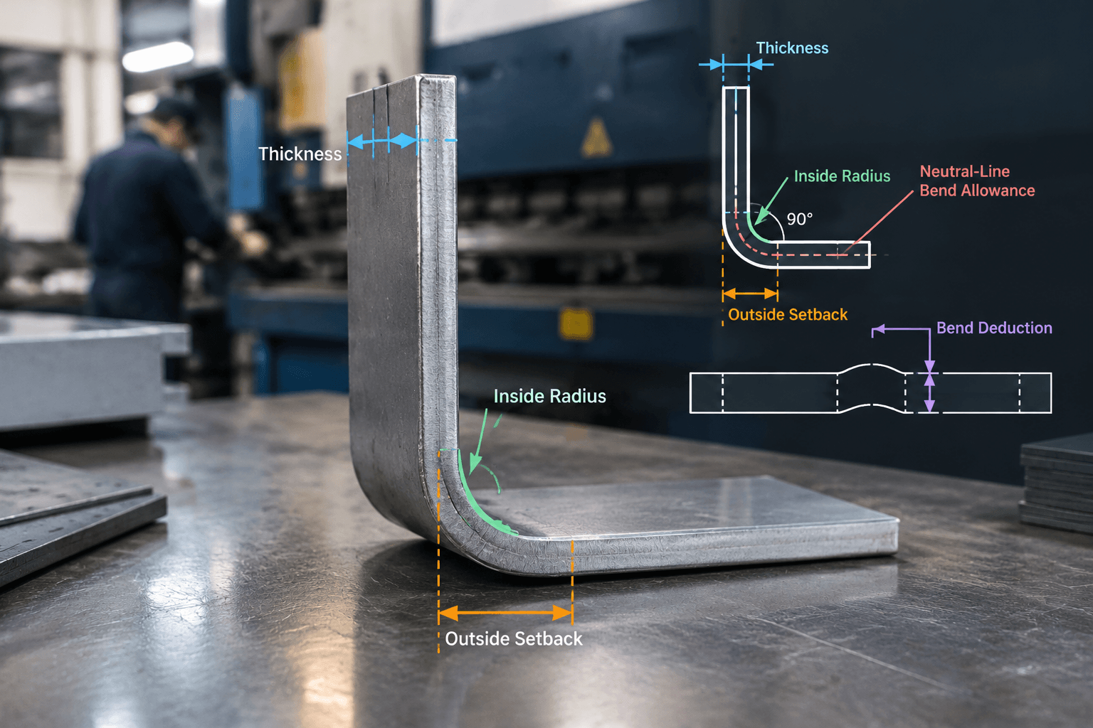
A 90 degree bend deduction is the value subtracted from the sum of two selected outside flange dimensions to calculate the flat-pattern length for one 90-degree sheet-metal bend. Use BD = 2 × OSSB − BA, where the 90-degree bend allowance is BA = π/2 × (inside radius + K-factor × thickness); the correct result depends on the material condition, thickness, inside radius, tooling, angle convention, and dimensional convention used by the chart or CAD system.
What a 90-Degree Bend Deduction Chart Actually Gives You
A 90 degree bend deduction chart is a controlled lookup reference for flat-pattern development. It should provide either a bend deduction (BD) value to subtract from formed outside dimensions or a bend allowance (BA) value to add between bend tangency locations. These outputs are related, but they are not interchangeable.
Bend deduction: BD = 2 × OSSB − BA
90-degree bend allowance: BA = π/2 × (R + K × T)
| Term | Plain-language meaning | Role in the flat pattern |
|---|---|---|
| Bend deduction (BD) | The amount removed from the sum of two selected outside dimensions. | Used when the drawing and flat-pattern method use outside dimensions. |
| Bend allowance (BA) | The developed length of the bend along the neutral line. | Used to bridge the two straight flange portions at the bend. |
| Outside setback (OSSB) | The distance from the outside mold line to the bend tangency reference under the selected convention. | At a 90-degree bend, it is commonly based on the outside bend radius, subject to the convention in use. |
| Neutral line | The layer within the material that is neither stretched nor compressed during bending. | Its arc length is the bend allowance. |
| K-factor | The neutral-line location expressed as a fraction of material thickness from the inside bend surface. | Used in a calculated BA when a validated table value is unavailable. |
For a 90-degree bend using an outside-radius interpretation, OSSB is generally the outside bend radius: R + T. This does not make BD universal. A different alloy, temper, thickness, punch radius, Vee-die opening, forming method, or approved shop table can produce a different validated value. Confirm whether the chart measures angle from the flat or from the formed condition, and confirm whether dimensions are inside, outside, tangent, or mold-line dimensions before applying its result.
90-Degree Bend Deduction Chart Template: Inputs to Match Before Lookup
A useful PDF or Excel chart is not automatically applicable simply because it is labeled “90 degree bend deduction.” The row must match the bend condition represented by the part and the intended press-brake setup. The following is a chart template, not a populated universal data table. Numerical rows should carry a source, revision, and validation note from the relevant fabrication workflow.
90-Degree Bend Deduction Reference Chart: Match Inputs, Calculate the Result, and Check the Flat Pattern
| Material / temper | Thickness | Inside radius | Bend angle | Vee-die width | Units | BA output | BD output | Source / revision / validation note |
|---|---|---|---|---|---|---|---|---|
| Specify when relevant | Required | Required | 90 degrees only | Required, or designate no-Vee-die | Required | Validated value, if supplied | Validated value, if supplied | Required for populated rows |
How to read the row: First match material and temper where they affect the approved forming data. Then match nominal thickness, inside radius, and the chart’s angle definition. Finally, match the Vee-die width or opening when the bend is formed with a Vee die. If a part includes a bend made without a Vee die, use a deliberately designated blank or “no Vee-die” condition if the table supports one; do not assume a Vee-die row covers it.
The BA and BD columns should remain visibly separate. A chart may provide one or both values, but converting between them requires the same OSSB and dimension convention used to create the chart. File format is not validation: a bend deduction chart PDF and a bend deduction calculator Excel sheet are delivery formats, not proof that their values fit every material and tooling setup.
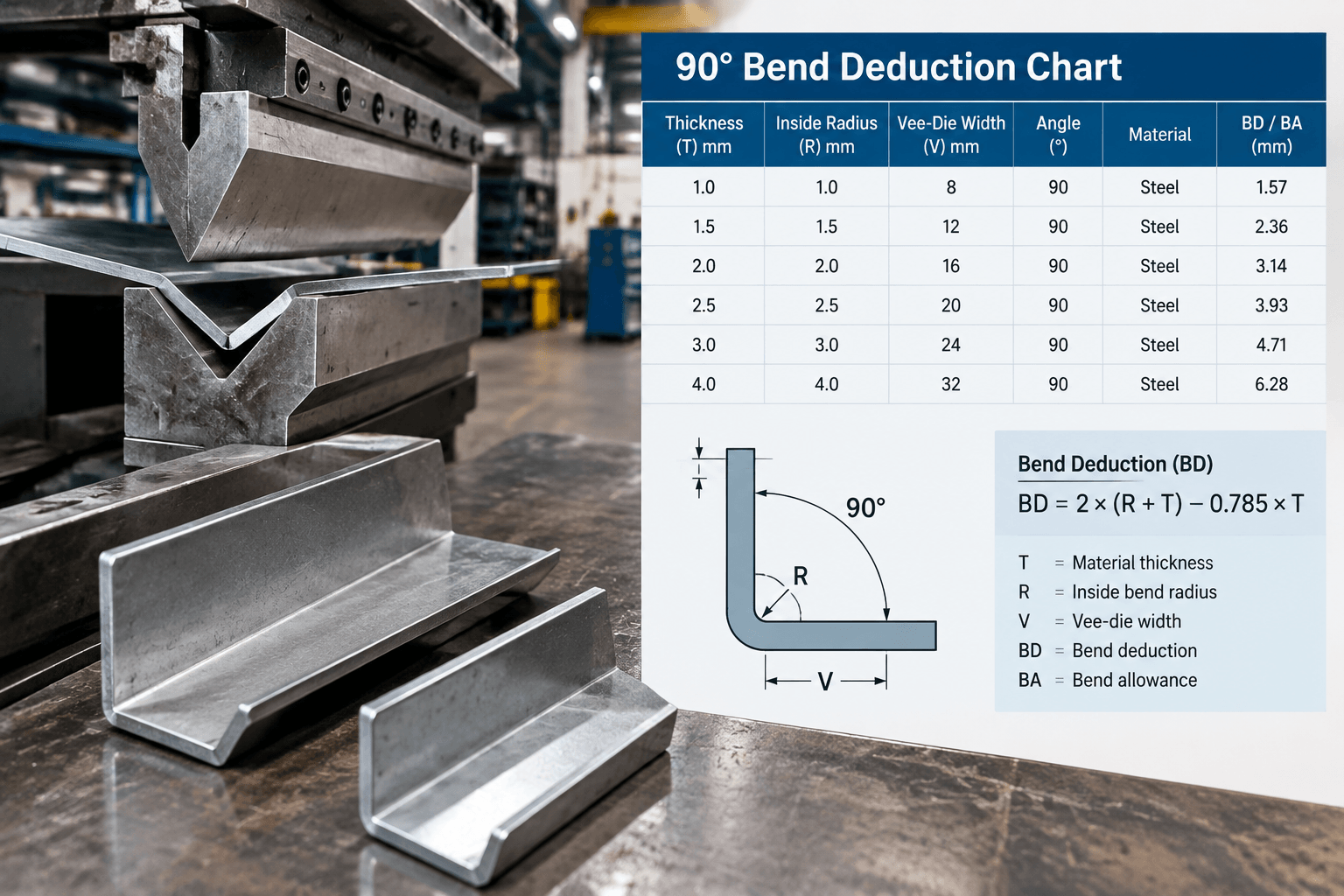
Manual Calculation for a 90-Degree Bend
When no exact approved chart row is available, a K-factor calculation can provide a controlled preliminary value. It is useful for design review, but it should not be presented as a substitute for a validated material-and-tooling-specific table. Keep every input in one unit system before substituting values.
For a 90-degree bend:
BA = π/2 × (R + K × T)
For the outside-radius OSSB convention at 90 degrees: OSSB = R + T
BD = 2 × (R + T) − BA
Illustrative calculation only: Assume a design uses T = 1.00 mm, R = 1.50 mm, and a documented provisional K-factor of 0.40. These are calculation assumptions, not Yishang production values or a recommendation for any material.
- Calculate bend allowance: BA = π/2 × (1.50 + 0.40 × 1.00) = π/2 × 1.90 = 2.985 mm, rounded here to three decimals.
- Calculate outside setback under the stated convention: OSSB = 1.50 + 1.00 = 2.50 mm.
- Calculate bend deduction: BD = 2 × 2.50 − 2.985 = 2.015 mm.
- For two outside flange dimensions of 30.00 mm and 40.00 mm, the illustrative flat length is 30.00 + 40.00 − 2.015 = 67.985 mm.
That final subtraction is valid only because the example consistently uses an outside-dimension convention. A drawing dimensioned to inside faces, tangent points, or another reference system requires the corresponding flat-pattern equation. Do not mix an outside-dimension BD with inside dimensions simply because both describe the same formed feature.
Choose Between a Bend Table, K-Factor, and Manual Override
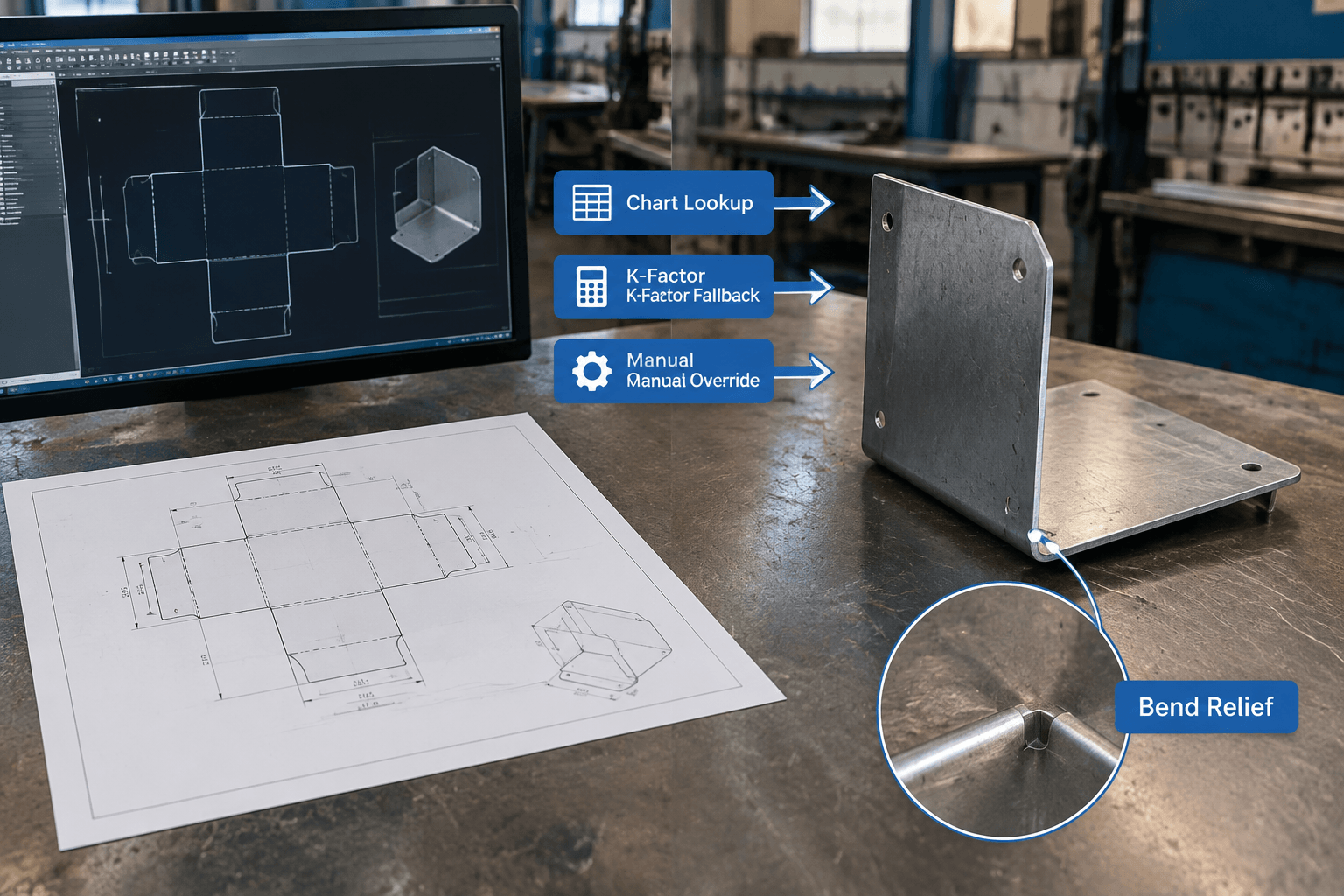
The preferred method depends on whether the bend condition is fully covered by controlled data. CAD systems may use different fallback behavior, so an absent row can lead to a default K-factor calculation, an unfold warning, an error, or another configuration-dependent result.
| Condition | Recommended method | Control point |
|---|---|---|
| Exact match for material, thickness, radius, angle, and Vee-die condition | Use the validated bend-table row. | Confirm units, revision, and dimensional convention. |
| Near match with a documented interpolation rule | Use only the approved interpolation method. | Record the source rows and the resulting value. |
| No assigned table, but a provisional design calculation is needed | Use the configured default K-factor calculation. | Verify the software setting and treat the output as provisional until confirmed. |
| Known approved part-specific value differs from the table or default | Apply a manual BA or BD override. | Document why it overrides the normal method and retain the value with the design record. |
| Thickness, radius, angle, Vee-die width, or no-Vee-die condition is missing | Stop and resolve the missing condition. | Do not silently substitute the nearest unrelated row. |
A manual override should be intentional rather than a hidden correction. It is appropriate when an approved value exists for a specific formed condition, but the drawing, model, and manufacturing record should identify which value was overridden and why. This matters on custom metal bracket drawings, where a short flange can make an incorrect bend value more visible in the final geometry.
Validation Gate Before You Unfold or Release the Flat Pattern
Run a short condition check before releasing the flat pattern. It is more effective to identify a missing table row during design than to discover that the model and intended bend setup use different assumptions.
| Check | What to verify | Action when it does not agree |
|---|---|---|
| Material condition | Material and temper match the table or documented calculation basis. | Request the correct controlled value or clarify the intended material. |
| Geometry | Thickness, inside radius, and angle match every bend condition. | Add or obtain coverage; do not reuse an unmatched row. |
| Tooling | Vee-die width is specified where relevant, or the bend is identified as no-Vee-die. | Clarify the process condition before finalizing the unfold. |
| Convention | Chart angle definition, units, sign convention, and inside/outside dimensioning agree with the drawing. | Convert through a documented method or correct the setup. |
| Physical confirmation | An approved supplier value or physical trial, where available, agrees with target formed dimensions. | Update the documented bend value rather than silently changing the model. |
Bend relief belongs in this review, but as a separate geometry decision. Relief can reduce tearing, distortion, or material interference near a bend termination; it is not an input to BA, BD, or K-factor by definition. For parts such as custom sheet metal enclosures, review relief geometry independently from the bend table because both can affect whether the part forms as intended.
If the table lacks a needed thickness, radius, angle, or tooling entry, provide the 2D drawing or flat pattern, material and thickness, inside radius, target bend angle, and Vee-die width, tooling information, or current bend table if known. Yishang supports B2B OEM and ODM custom manufacturing and can help review whether the bend inputs and deduction method are complete before production.
Frequently Asked Questions
How do I calculate bend deduction for a 90-degree bend?
Use BD = 2 × OSSB − BA. Under an outside-radius OSSB convention for a 90-degree bend, OSSB is typically R + T, while BA = π/2 × (R + K × T). Use consistent units and confirm that the resulting BD fits the drawing’s outside-dimension convention.
What is the difference between bend deduction, bend allowance, and K-factor?
Bend allowance is the developed arc length along the neutral line. Bend deduction is the amount subtracted from selected formed outside dimensions to obtain the flat length. K-factor locates the neutral line within the thickness and is one input used to calculate bend allowance; it is not a bend allowance or deduction by itself.
Do I need the Vee-die width to use a bend deduction chart?
Use it when the chart identifies Vee-die width as a lookup condition. Tooling can affect the validated flat-pattern result, so a row for a different Vee-die opening should not be assumed equivalent. Bends formed without a Vee die need a separately designated no-Vee-die condition when the table distinguishes them.
What should I do when my thickness, inside radius, or tooling condition is missing from the table?
Do not silently choose a nearby row. Check whether an approved interpolation rule exists, whether the CAD configuration permits a documented K-factor fallback, or whether a controlled manual override is available. Otherwise, request clarification before unfolding or releasing the flat pattern.
Is bend relief included in a 90-degree bend deduction calculation?
No. Bend relief is a local feature near a bend end, while bend deduction describes developed length under a stated dimensional convention. Review relief separately for geometry and forming needs, then calculate or look up the BD using the applicable bend conditions.