
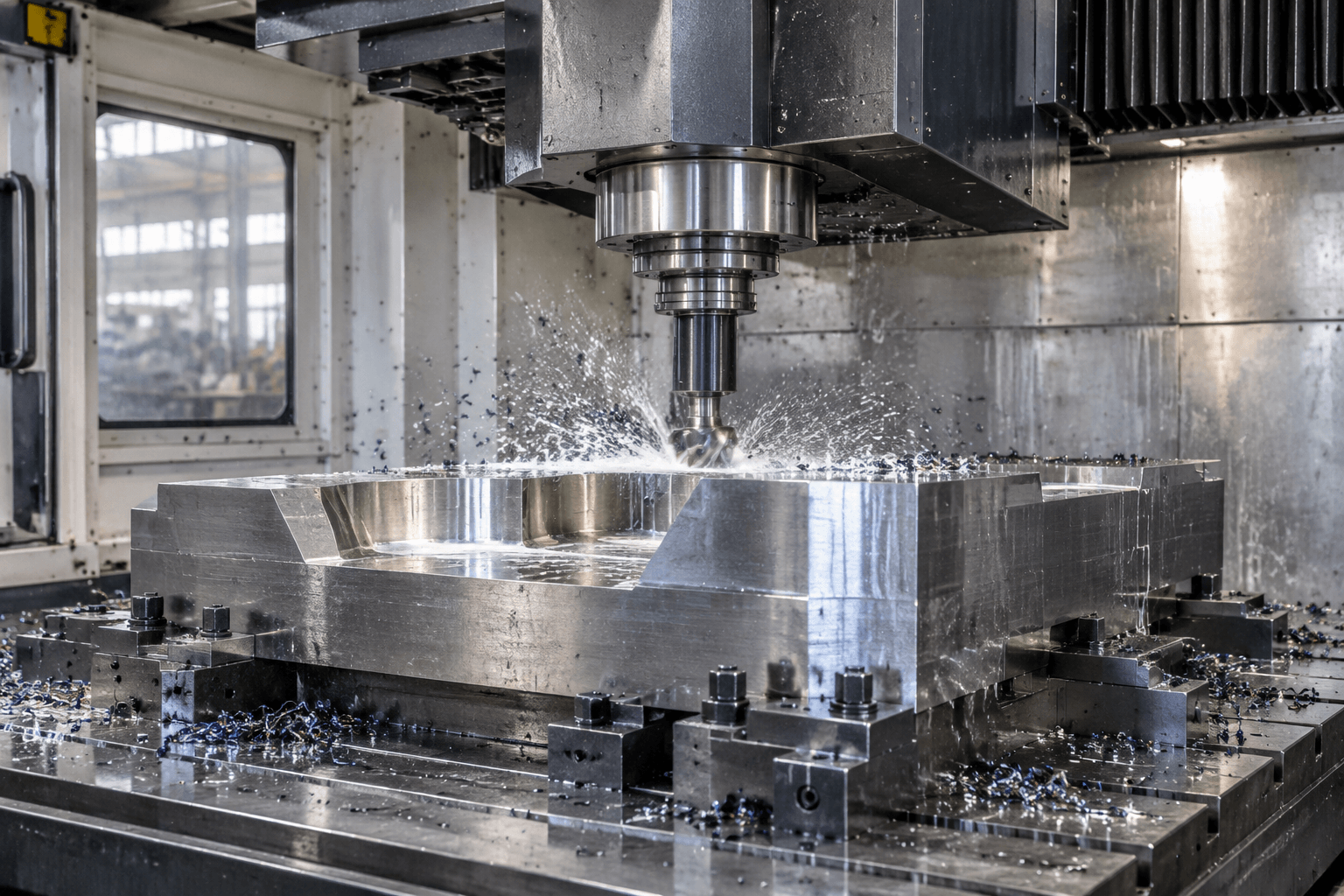
Advanced milling machines for heavy duty work are CNC machines designed to maintain stable cutting under sustained load, especially when machining large parts, difficult alloys, deep features, or components that require long cycles. The description refers to machine behavior, not simply machine size, maximum spindle speed, axis count, or a collection of advanced control features.
A suitable machine must deliver usable spindle torque and power while its structure, guideways, fixtures, tooling, coolant system, and thermal controls resist deflection and heat-related change. Nominal specifications establish basic limits, but they do not by themselves show how the machine will perform during a demanding cut. Meaningful evaluation therefore requires examining the complete cutting system under conditions relevant to the intended part.
What Makes a Milling Machine Heavy-Duty?
General-purpose and heavy-duty milling overlap, but their operating demands differ. A general-purpose machine may perform well on moderate cuts and shorter cycles. Heavy-duty operation places greater and more sustained loads on the spindle, frame, axes, tool, fixture, and workpiece.
Typical heavy-duty requirements include removing substantial amounts of material from steel, cutting titanium or other difficult alloys, machining hardened steel with appropriate tools and strategies, supporting a large workpiece and fixture, or maintaining feature relationships throughout a long cycle. Some projects combine several of these conditions.
The word advanced can describe multi-axis motion, process monitoring, thermal compensation, probing, adaptive controls, or sophisticated tool management. Those features may improve access, consistency, or automation, but they do not automatically provide heavy-duty capability. A highly automated machine can still be limited by insufficient torque, structural compliance, poor chip removal, or a work envelope that becomes too small after fixtures and tools are installed.
The practical question is not whether a machine carries an advanced label. It is whether the machine and its supporting systems can sustain the required process without unacceptable chatter, deflection, thermal drift, tool instability, or loss of dimensional control.
The Mechanical Foundation of Stable Cutting
Spindle torque and power delivery
Maximum spindle power is only one part of the picture. Engineers also need to consider where that power is available across the spindle-speed range and how much torque the spindle can provide at the speeds required by the cutter and material.
Heavy roughing with a large cutter may require strong torque at relatively low or moderate speed. Smaller tools and finishing operations may call for higher rotational speed but lower cutting force. A published peak value does not reveal whether the spindle can maintain the required output throughout a long cut. Continuous or duty-related information, when supplied under clearly defined conditions, is more useful than an isolated maximum.
This is why maximum spindle speed alone is not a reliable heavy-duty indicator. Speed can benefit particular tools and materials, but it cannot compensate for inadequate low-speed torque or unstable power delivery during force-intensive cutting.
Structural rigidity and force paths
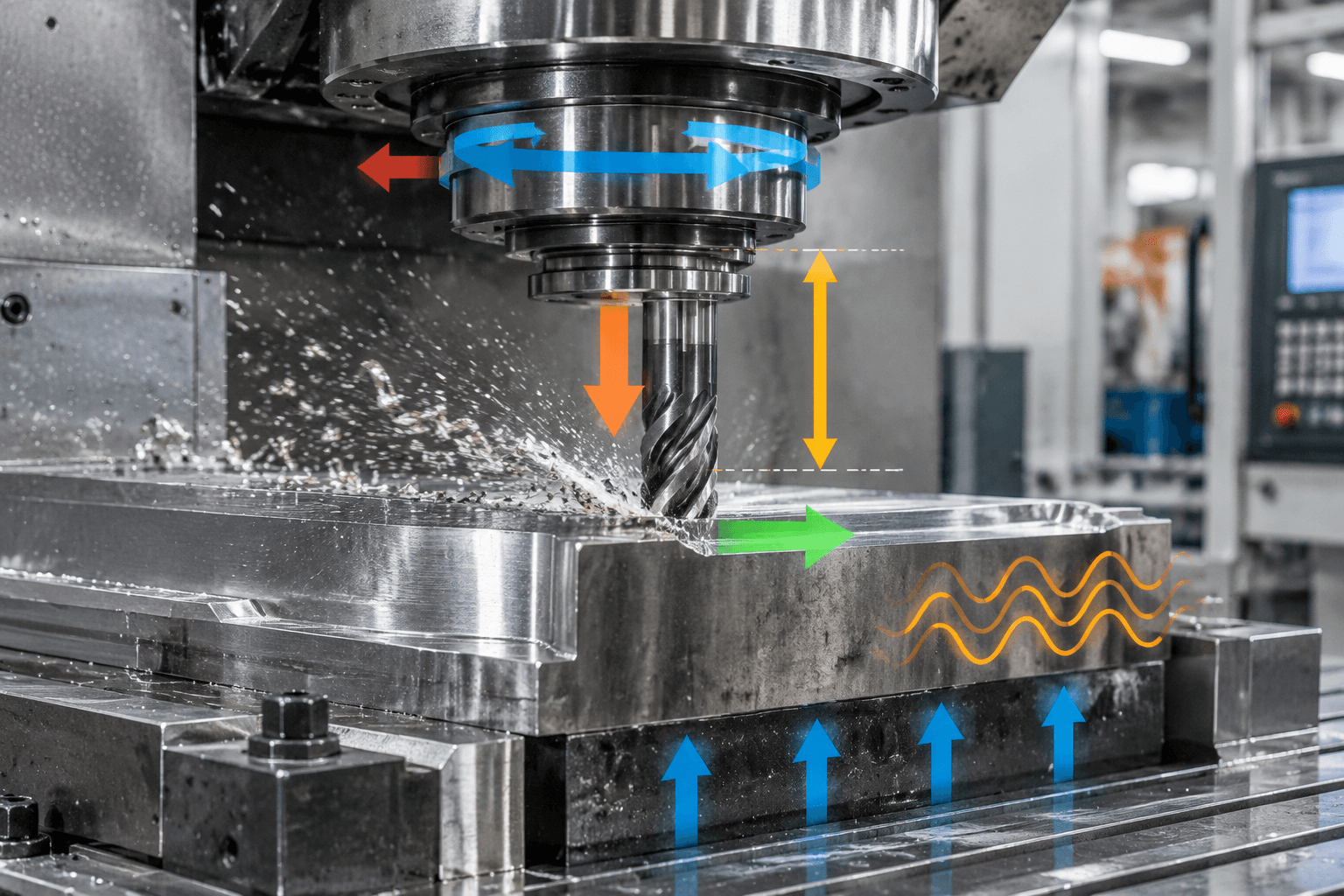
Cutting force travels through the tool, spindle, machine structure, axis components, table, fixture, and workpiece. Compliance at any point can allow relative movement between the cutting edge and the part. The result may be chatter, dimensional variation, accelerated tool wear, poor surface condition, or a need to reduce cutting parameters.
Machine mass can help damp vibration, but mass alone does not define rigidity. Frame geometry, joint design, spindle support, guideway behavior, axis position, table support, and the distance between the cutter and the machine structure all affect stiffness. Tool and fixture choices are equally important. A rigid machine cannot fully overcome an unnecessarily long tool, a flexible fixture, or weak support beneath the workpiece.
Tool overhang deserves particular attention. As the cutting edge moves farther from its support, bending leverage increases. Deep pockets and tall workpieces may therefore impose stability limits even when the spindle has enough power. A process may need shorter tools where possible, staged tool lengths, additional workpiece support, or a different setup orientation.
Vibration control under changing conditions
Machine stability is not constant across every spindle speed, axis position, tool assembly, and workpiece geometry. A cut that is stable near the center of the table may behave differently when axes are extended or when a rotary unit raises the part. Material removal can also reduce the stiffness of the workpiece as machining progresses.
Heavy-duty capability should consequently be evaluated as an interaction among the machine, cutting tool, holder, fixture, part, and programmed toolpath. Reducing chatter may require changing tool engagement, spindle speed, feed, toolpath direction, or support conditions rather than relying on machine power alone.
Work Envelope, Table Capacity, and Axis Access
Published axis travels describe potential motion, but the usable machining envelope can be smaller. Fixtures occupy table area, tools require approach and withdrawal clearance, spindle heads have physical dimensions, and rotary axes consume space while changing the location and height of the workpiece.
Before considering a part feasible, compare its dimensions and mass with all of the following:
- Axis travels and the positions available throughout those travels
- Table dimensions, support area, and stated load conditions
- Fixture footprint, clamping access, and support beneath the part
- Workpiece height and clearance beneath the spindle or head
- Tool-holder length, tool-change clearance, and safe approach paths
- Space consumed by rotary tables, tombstones, angle plates, or probes
- Whether chips and coolant can escape from the selected orientation
Table load should not be treated as permission to place any component of the stated mass anywhere on the table. The distribution of the workpiece and fixture, their combined center of gravity, and the machine manufacturer’s loading conditions remain relevant.
Three-axis machining
A three-axis machine can be an effective choice when major features are accessible from a limited number of directions. Consider a large steel plate with pockets, bolt patterns, and reference surfaces on one primary face. If it can be supported rigidly and the tools can reach the features, three-axis machining may provide a direct force path and straightforward fixturing.
Features on other faces may require additional setups. Each reclamping operation introduces new locating and verification requirements, so setup count matters when relationships between faces are critical.
Four-axis machining
A fourth axis can index or rotate a component to expose multiple sides. This can reduce manual repositioning for parts with circumferential features, repeated side details, or machining distributed around a common axis. Its value depends on the rotary unit’s capacity, support arrangement, available torque, and the space left for the part and tools.
For a long component, rotary access may simplify feature alignment, but the unsupported span and tailstock or auxiliary support still influence cutting stability. Additional axis capability does not remove the need for a rigid load path.
Five-axis machining
Five-axis motion can improve tool access to angled faces, deep cavities, compound surfaces, and features that would otherwise require several setups. It may also permit a shorter tool orientation by tilting the part or spindle toward the cutting region.
Five-axis is not automatically better for every heavy cut. Rotary-axis capacity, interference zones, changing leverage, fixture location, and reduced usable envelope can constrain the process. A simple, force-intensive operation may be better served by a rigid three-axis setup, while complex geometry may justify simultaneous or indexed five-axis access. The right configuration follows the part geometry and load case rather than the axis count alone.
Systems That Support Long, Demanding Cycles
Tool capacity and tool management
Long cycles may involve roughing tools, semi-finishing and finishing tools, drills, thread-making tools, chamfer tools, probes, and duplicate tools for wear management. Magazine capacity should be compared with the actual process plan rather than considered as an isolated number.
Tool-change reliability, maximum permitted tool size and mass, adjacent-pocket restrictions, holder compatibility, and replacement-tool logic can all affect unattended or extended operation. Tool measurement and breakage detection may help identify process changes, but their value depends on how they are integrated into the machining plan.
Chip evacuation
High material removal creates a chip-handling problem as well as a cutting problem. Chips that remain in a pocket can be recut, interfere with coolant, damage a finished surface, or accumulate around the tool and fixture. The enclosure layout, internal guarding, augers or conveyors, coolant flow, and workpiece orientation influence whether chips move away from the cutting zone.
Deep cavities and horizontal surfaces can trap chips even when the machine has a capable conveyor. Toolpaths, flushing direction, air use where appropriate, and planned chip-clearing movements may therefore be necessary. Chip volume and chip shape vary with the material and cutting strategy, so evacuation should be assessed for the intended operation.
Coolant delivery and filtration
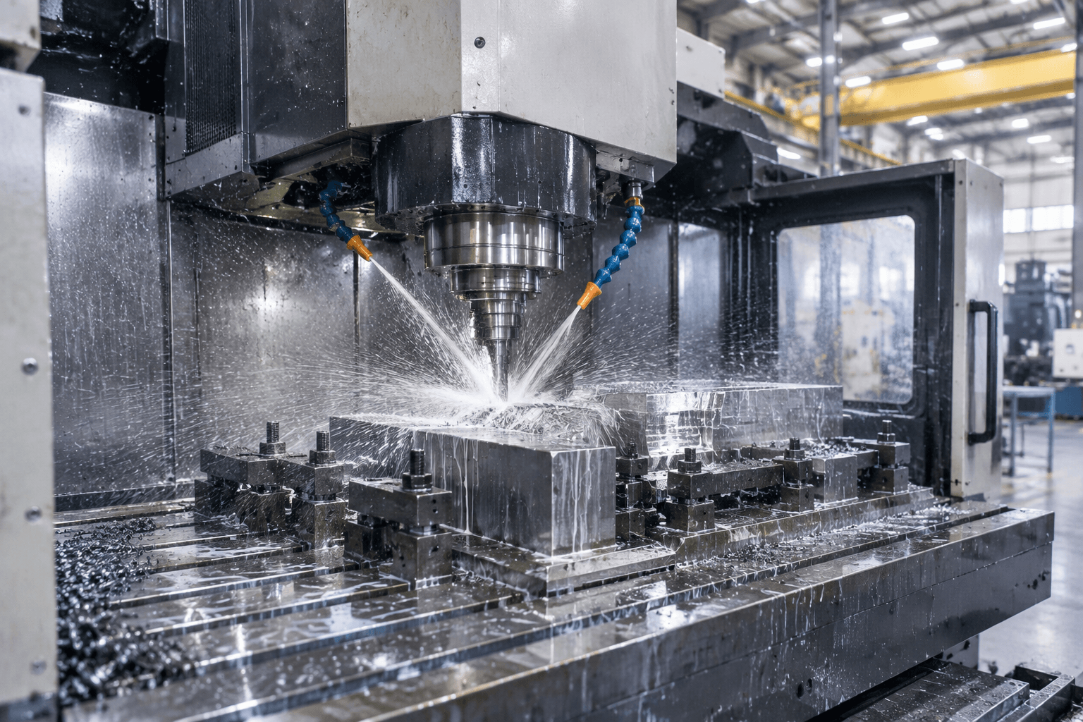
Coolant must reach the cutting edge to provide useful lubrication, cooling, and chip transport. Delivery pressure is relevant, but nozzle position, flow, through-tool availability, passage size, filtration, and the ability to maintain coolant condition also matter.
Titanium and other heat-sensitive cutting applications can place particular emphasis on managing heat at the cutting zone. Hardened materials may require a different combination of tooling, cutting parameters, and coolant strategy. No single delivery method is universally appropriate; it should match the tool, operation, material, and chip-control requirement.
Thermal management
Heat arises from cutting, the spindle, axis motion, motors, coolant, and the surrounding environment. During a long cycle, temperature changes can alter the relative positions of the spindle, tool, table, fixture, and workpiece.
Spindle temperature control, coolant temperature management, machine warm-up procedures, thermal compensation, and a reasonably stable environment can reduce variation. They do not eliminate heat-related effects, and compensation quality depends on the conditions represented by the machine’s model or measurement system. Process planning should also consider heat generated in the workpiece and dimensional changes that occur as material is removed.
Heavy-Duty Milling Capability: What Specifications Reveal—and What They Do Not
| Capability indicator | What it can reveal | What it does not establish by itself |
|---|---|---|
| Spindle torque and power curves | Available output across specified speed ranges | Stability of the entire tool-machine-fixture system |
| Maximum spindle speed | Upper rotational limit for compatible operations | Heavy-cutting strength or low-speed torque |
| Machine construction and mass | Context for structural support and damping | Rigidity at every axis position or tool extension |
| Axis travels | Nominal motion range | Usable envelope after accounting for fixtures, tools, and interference |
| Table dimensions and load rating | Basic workholding area and stated load capacity | Suitability of every load distribution or setup |
| Axis count | Potential directions of tool access and motion | That fewer setups or better results are guaranteed |
| Tool-magazine capacity | Number of tool positions under stated conditions | Compatibility with every large or heavy tool assembly |
| Coolant and chip systems | Available methods for cooling and chip transport | Effective evacuation from every cavity and orientation |
| Positioning accuracy and repeatability | Machine-axis performance under defined test conditions | Finished-part accuracy during a specific loaded process |
Evaluating Accuracy During Loaded Operation
Positioning accuracy, repeatability, and finished-part accuracy are related but different. Positioning accuracy concerns how closely an axis reaches a commanded position under stated test conditions. Repeatability concerns how consistently it returns to a position. Finished-part results also depend on cutting force, tool deflection, tool wear, spindle condition, fixture movement, workpiece stress, temperature, programming, and measurement method.
Accuracy claims should therefore be reviewed with their test conditions. Useful context includes the measurement method, machine state, environmental conditions, axis positions, warm-up status, load condition, and whether the value applies to an individual axis or a machined test piece. Values obtained under different standards or procedures may not be directly comparable.
Long-cycle evaluation should address when critical features are produced and how temperature and tool condition may change between them. In-process probing can detect selected positions or features, but it does not replace an appropriate final inspection plan. Depending on the feature, verification may involve calibrated dimensional instruments, height or surface measurement equipment, gauges, or coordinate measurement. The method must be suitable for the geometry and drawing requirement.
Matching Machine Behavior to the Part
A sound capability decision begins with the component rather than a machine ranking. Review these factors together:
- Material and condition: Identify the alloy, hardness or heat-treatment state, stock form, and any behavior that affects cutting forces, heat, or distortion.
- Part dimensions and mass: Include raw stock, fixture mass, lifting needs, support points, and the space required for tool access.
- Critical geometry: Separate material-removal features from tolerance-critical bores, surfaces, interfaces, and relationships between faces.
- Axis access: Determine whether three-axis machining is sufficient or whether indexing or simultaneous multi-axis motion meaningfully reduces setups or tool extension.
- Cycle duration and production pattern: Consider tool life, duplicate tooling, chip accumulation, thermal equilibrium, monitoring, and operator intervention over the expected run.
- Volume and change frequency: A repeat program may justify different fixturing or automation than a one-off part or frequently revised design.
- Space and budget: Machine footprint, foundation needs, utilities, work handling, tooling, fixturing, inspection, and maintenance are tradeoffs alongside acquisition cost.
Material also changes the balance among these factors. Steel roughing may emphasize torque, rigidity, and chip volume. Titanium can make heat control, tool engagement, and process stability especially important. Hardened steel places strong demands on tooling, toolholding, machine condition, and controlled cutting strategies. Other difficult alloys may combine high cutting forces, heat concentration, abrasive wear, or work-hardening behavior.
Not every heavy component is primarily a milling project. Cylindrical parts dominated by concentric diameters may be better suited to CNC turning, with milling used only for secondary flats, holes, or slots. Fabricated structures may require welding and forming first, followed by limited machining of mounting surfaces or interfaces. For example, fabricated metal brackets built to drawings may include holes, slots, or mounting features, but fabrication and milling remain distinct processes. Similar process separation matters for components used in material-handling and logistics equipment.
Discuss the Manufacturing Fit of a Heavy-Duty Part
If you have an actual component requirement, share the part drawing or 3D model, material specification, critical dimensions and tolerances, and expected order quantity or production pattern. An engineering-fit discussion can then focus on whether the geometry and critical features are suited to milling, require multiple machining processes, or call for a different manufacturing route. This review does not require assuming that a particular machine configuration or immediate equipment purchase is the answer.
Where RFQ Assumptions Create Cost and Production Risk
Many sheet metal fabrication problems begin before production starts. If drawings, tolerances, finish expectations, material grades, or assembly requirements are unclear, suppliers may quote based on different assumptions. That can make prices difficult to compare and may lead to rework, cosmetic rejection, assembly misalignment, or production delays later.
For OEM buyers, the goal is not simply to request the lowest price. The goal is to make sure each supplier is quoting the same manufacturing reality. Before confirming an order, clarify which dimensions are fit-critical, which surfaces are cosmetic, whether prototypes must match batch-production conditions, and how finished parts will be inspected.
Frequently Asked Questions
What laser cutting precision details should buyers define before requesting a quote?
Buyers should define the functional requirement, drawing notes, critical dimensions, material or process expectations, and any inspection points related to laser cutting precision. This helps suppliers quote the same manufacturing scope instead of making different assumptions.
How can cut hole locations affect cost, fit, or lead time?
cut hole locations can change tooling, forming, welding, finishing, inspection, or rework requirements. If buyers do not clarify it early, two supplier quotes may look comparable while covering different production risks.
Why should bend-to-hole dimensions be reviewed before prototype approval?
bend-to-hole dimensions may look acceptable on a single sample but become harder to control during batch production. Buyers should confirm whether the prototype reflects the same process, finish, and inspection conditions expected for production.
What inspection points matter most for advanced milling machines for heavy duty projects?
Important inspection points usually include fit-critical dimensions, holes or mating areas, cosmetic surfaces, finish build-up, welded or formed features, and any dimensions that affect downstream assembly. These points should appear in the RFQ or drawing notes.
How can buyers reduce batch consistency risk before batch production?
Buyers can reduce risk by clarifying drawings, locking key material and finish assumptions, defining inspection timing, approving a representative sample, and confirming which dimensions or surfaces require tighter process control.
How can Yishang help review advanced milling machines for heavy duty requirements?
Yishang can review drawings, RFQ notes, material requirements, tolerance expectations, finish details, samples, and assembly needs to identify unclear assumptions before quoting or batch production.