
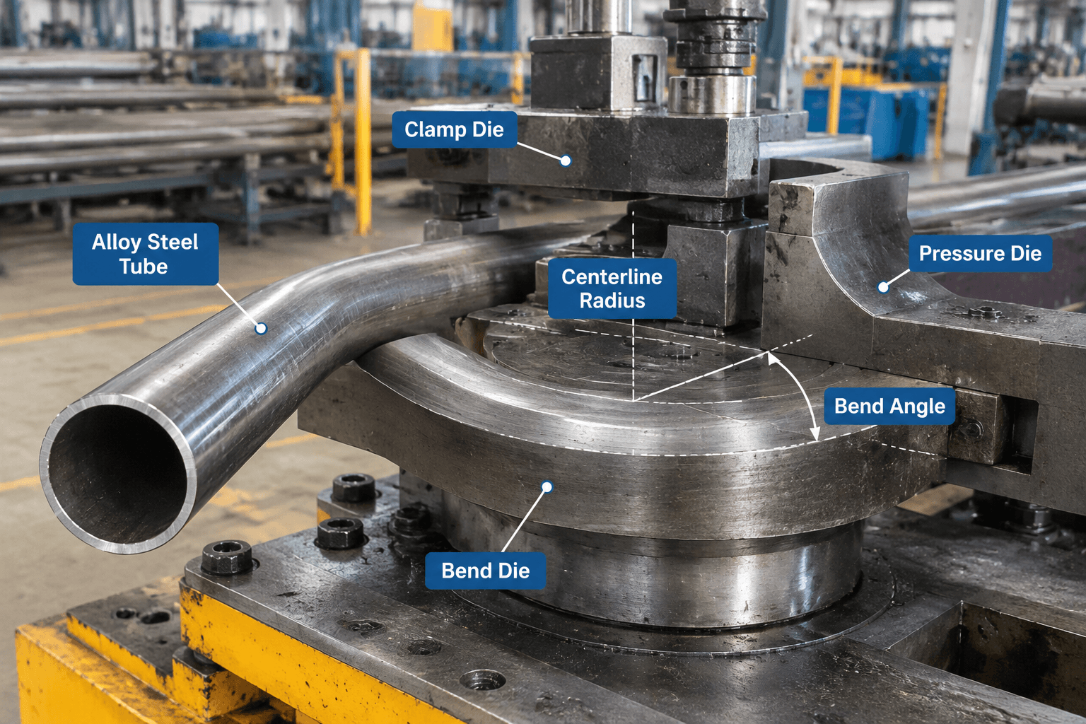
Alloy steel tube bendability cannot be determined from the material name alone. A manufacturability review must consider the alloy grade, supplied condition, outside diameter, wall thickness, centerline radius, bend angle, straight tangent lengths, dimensional interfaces, and acceptance criteria together. Two tubes with identical dimensions may bend differently when their grades, hardness, heat-treatment states, manufacturing routes, or dimensional variation differ.
A useful bend specification therefore defines both the starting material and the required finished geometry. It should also state how bend location, angle, radius, profile, and orientation will be measured. Without those details, a drawing may describe the intended shape but leave the manufacturer unable to select tooling, evaluate deformation, or establish an inspection method.
What Must Be Defined Before Alloy Steel Tube Bending?
Begin by confirming that the part is actually tube. Tube is commonly specified by outside diameter and wall thickness because its external geometry and structural section are important to the finished part. Pipe is generally identified by nominal pipe size and schedule; its nominal designation should not be treated as its measured outside diameter or wall thickness without checking the applicable product specification. Solid bar has no internal bore and responds differently during forming, so bar-bending assumptions do not define tube-bending requirements.
The material description must identify the alloy steel grade and the governing material specification where applicable. “Alloy steel” by itself is too broad for process planning. The manufacturer also needs the supplied condition, such as the documented heat-treatment state, hardness range, or other condition identified by the material documentation. Do not assume that every alloy steel grade, or every condition of the same grade, has equivalent ductility or springback behavior.
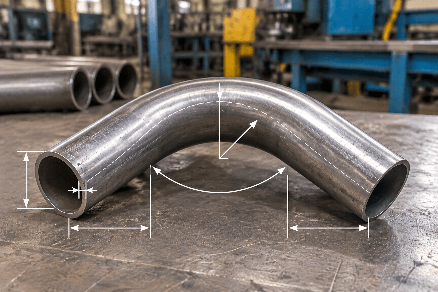
The drawing or bend schedule should then define the geometry:
- Outside diameter: the measured external tube diameter rather than a nominal pipe designation.
- Wall thickness: the specified starting wall, including any relevant permitted material variation.
- Centerline radius: the radius measured to the tube centerline, clearly distinguished from inside or outside bend radius.
- Bend angle: the required angular change, with the drawing convention and measurement method made clear.
- Tangent points: the locations where the straight tube transitions into and out of the bend.
- Straight tangent lengths: the usable straight sections before, between, and after bends.
- Bend orientation: the rotational relationship between multiple bends and any holes, slots, seams, brackets, or end features.
Short tangents, closely spaced bends, or end features near a tangent point may limit how the part can be gripped and supported. These details should be reviewed before tube cutting, holemaking, or end preparation is finalized. A feature that is easy to locate on a flat drawing may interfere with the clamp die, pressure die, mandrel, or inspection fixture during production.
Why Alloy Grade and Supplied Condition Change Bend Behavior
Tube dimensions describe the section being formed, but the material condition influences how that section responds to tensile and compressive strain. During bending, the outside wall stretches, the inside wall compresses, and the cross-section may tend to distort. The amount and location of deformation depend on the combined material, geometry, tooling, and process conditions.
| Input to Confirm | Why It Matters | Documentation or Review Input |
|---|---|---|
| Alloy grade and material specification | Different compositions and specified property requirements can produce different forming responses. | Drawing callout, purchase specification, and material documentation |
| Supplied condition | Heat-treatment state, strength, ductility, and hardness can affect cracking risk, required force, and springback. | Condition designation, hardness information, or applicable certificate data |
| Tube manufacturing route | Seam condition, residual stress, surface condition, and dimensional consistency may influence forming and orientation decisions. | Applicable tube specification and supplier documentation |
| Outside diameter and wall variation | Variation changes the amount of material available to resist flattening, thinning, and local instability. | Specified limits and incoming inspection data where required |
| Surface condition | Damage, scale, seams, or other surface features may become more significant in highly strained areas. | Material condition requirements and visual inspection criteria |
Heating should not be treated as an automatic solution to difficult bending. Heat can alter the local or overall material condition, surface state, dimensional response, and subsequent heat-treatment requirements. If a process includes heat, its effect must be evaluated against the material specification and the finished-part requirements. Post-bend heat treatment should likewise be specified only when required by the material, engineering design, or governing procedure.
How Bend Geometry Determines Tooling and Process Support
Centerline radius, wall thickness, bend angle, tangent length, and part layout work together. A tighter radius increases deformation demand. A thinner wall generally provides less resistance to cross-sectional distortion. A larger bend angle exposes more tube length to the forming operation and can amplify springback or profile-control concerns. Multiple bends add grip, clearance, and rotational-orientation requirements.
In rotary-draw bending, the bend die establishes the bend path, the clamp die holds the tube against it, and the pressure die supports and feeds the straight section as the bend forms. Depending on the material and geometry, internal mandrel support may help control collapse or flattening, while a wiper die may help manage compression-side wrinkling near the tangent. The need for these tools cannot be decided from the keyword “alloy steel” alone.
| Design Condition | Manufacturing Concern | Review Question |
|---|---|---|
| Small centerline radius relative to tube size | Higher outside-wall strain, inside-wall compression, and profile distortion | What tooling contact and internal support are needed for the stated grade and condition? |
| Relatively thin wall | Flattening, collapse, wrinkling, or excessive thinning | How will the cross-section be supported and inspected? |
| Large bend angle | Accumulated deformation and springback compensation | How will final angle and tangent geometry be verified? |
| Short straight tangent | Insufficient grip or interference with tooling | Is extra process stock needed, and may it be trimmed after bending? |
| Closely spaced multiple bends | Tool clearance, repositioning, and dimensional accumulation | Is the bend sequence feasible without interfering with completed bends? |
| Features located near a bend | Feature distortion or conflict with clamping and support | Should the feature be added before or after bending? |
| Multiple bend planes | Rotation error between bends | What datum controls clocking and how will orientation be measured? |
For example, a single-bend tube with generous straight lengths presents a different planning problem from a multi-bend member whose final tangent must align with mounting holes. In the second case, angle alone is not sufficient: bend location, rotation between bend planes, end position, and assembly interfaces must be controlled as a connected dimensional system.
This relationship is especially important when bent members become part of custom metal frames. A locally acceptable bend may still cause frame misalignment if tangent position, end orientation, or accumulated rotation is not tied to the assembly datums. Similar geometric controls can apply to formed components used in automotive and transportation equipment or material-handling and logistics equipment.
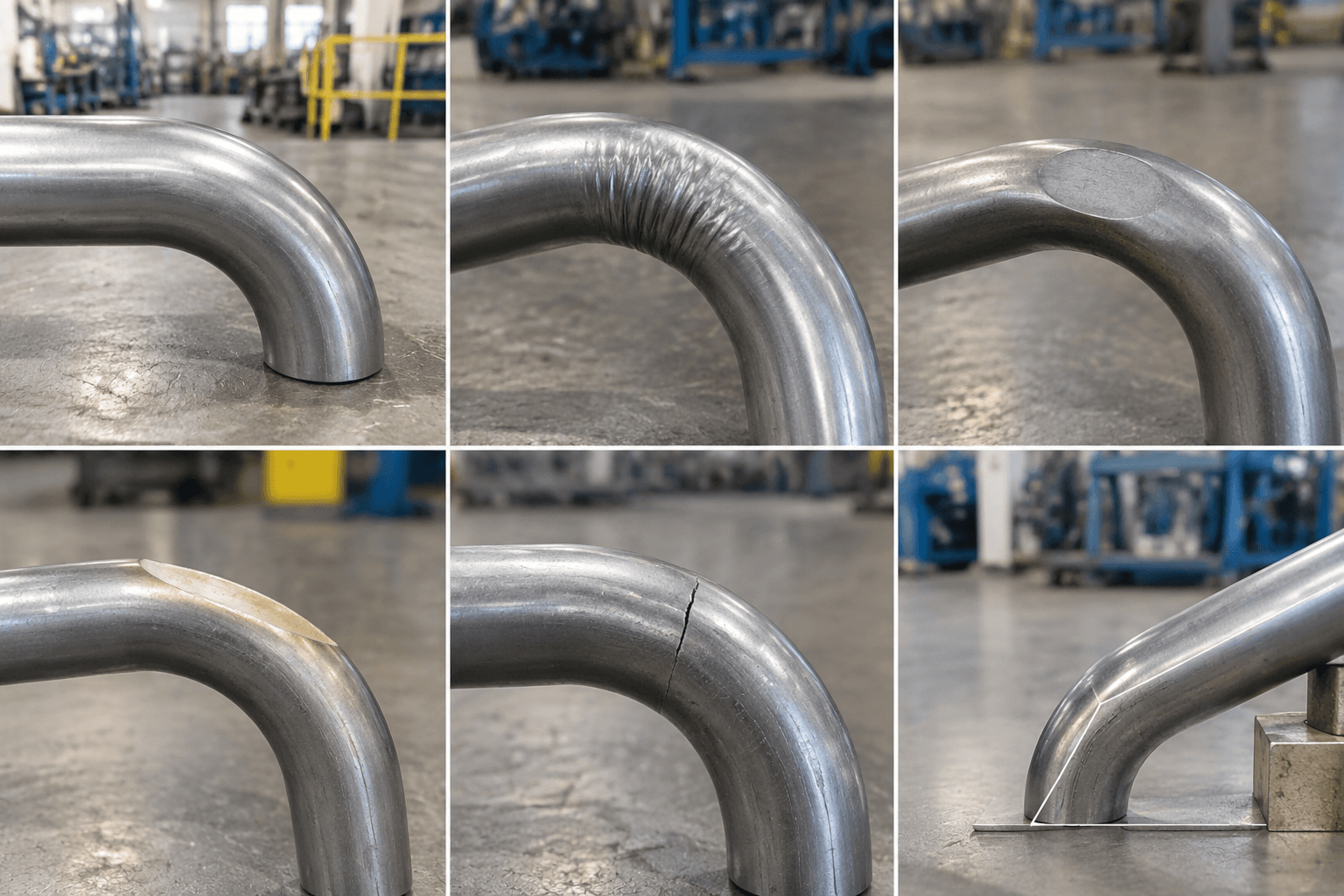
Diagnosing Common Alloy Steel Tube Bend Defects
Defect analysis should compare the original material and dimensions with the finished bend. Record where the defect appears, whether it is on the inside, outside, or side of the bend, and whether it is concentrated near a tangent or distributed through the arc. Tooling setup and material identification are necessary because similar visible defects can have different causes.
| Observed Condition | Possible Contributors | Review or Corrective Direction |
|---|---|---|
| Kinking or local collapse | Geometry beyond the support arrangement, insufficient internal support, grip loss, or inconsistent starting tube | Verify grade, condition, dimensions, tooling engagement, and support strategy before changing the drawing or process. |
| Wrinkling on the inside of the bend | Compression instability, inadequate wiper or mandrel control, poor pressure-die support, or setup mismatch | Inspect wrinkle location and tooling contact; review support and setup rather than merely increasing force. |
| Flattening or ovality | Cross-sectional distortion caused by radius, wall, material response, or insufficient support | Measure the profile at defined locations and evaluate tooling or geometry changes against functional limits. |
| Excessive outside-wall thinning | High tensile strain, material variation, tooling setup, or a demanding radius-and-angle combination | Measure wall at specified locations and determine whether the design limit or process setup is controlling the result. |
| Cracking | Insufficient ductility in the supplied condition, surface defects, excessive local strain, or an unsuitable process condition | Stop and confirm material identity, condition, surface state, crack location, and strain demand; heating should not be assumed to provide an acceptable repair. |
| Final angle outside requirement | Springback variation, inconsistent material condition, setup variation, or unclear measurement convention | Define the final-state measurement method and establish compensation from controlled process evidence. |
| Incorrect rotation between bends | Datum ambiguity, indexing error, grip movement, or accumulated positioning variation | Control clocking from a defined datum and inspect the relationship between bend planes or end interfaces. |
Do not accept or reject a bend solely from a general impression that it “looks round.” A small profile change may be important at a sealing, bearing, or assembly interface, while a visible but controlled change may be acceptable elsewhere if the drawing permits it. Acceptance must follow the part’s functional requirements.
How to Define and Measure Bend Acceptance
A bend drawing should use a datum scheme that allows the part to be located consistently for manufacturing and inspection. The datum may be based on an end face, a straight tube axis, a mounting feature, or another functional interface. For multi-bend parts, the drawing should prevent ambiguity about which bend or feature establishes rotational orientation.
Define the required output and its inspection method together:
- Bend location: dimension tangent points, bend centers, or functional end positions from identified datums.
- Bend angle: state whether it is determined from the axes of the straight tangents or another defined geometric method.
- Centerline radius: identify the radius convention and avoid mixing centerline, inside, and outside radius callouts.
- Cross-sectional profile: specify where flattening, ovality, or other profile variation is evaluated and what functional limit applies.
- Wall condition: identify measurement locations if minimum wall or thinning is critical to performance.
- Orientation: define clocking between bends and between bends and end features.
- Surface acceptance: describe whether tool marks, cracking, folds, or other visible conditions are prohibited or limited.
- Assembly interfaces: dimension end position, hole location, bracket orientation, or mating geometry when these control fit.
Inspection may use direct dimensional instruments, radius or profile templates, fixtures, gauges, or coordinate-based measurement, depending on the geometry and acceptance requirement. The drawing should not demand a characteristic without providing a stable reference and a practical way to verify it. For multi-bend parts, inspect representative first, intermediate, and final features rather than checking only the overall envelope.
Information Needed to Evaluate an Alloy Steel Tube Bend
| Specification Input | Information to Provide |
|---|---|
| Material | Alloy grade, governing specification, and required material documentation |
| Supplied condition | Heat-treatment state, hardness information, or other documented condition |
| Starting tube | Outside diameter, wall thickness, relevant dimensional limits, length, and manufacturing-route requirements if controlled |
| Bend geometry | Centerline radius, bend angle, tangent points, and straight lengths |
| Part layout | Number of bends, distances between bends, bend-plane rotation, end features, and nearby holes or attachments |
| Datums | References controlling bend location, clocking, end position, and assembly fit |
| Acceptance | Allowed angle, location, radius, profile, wall, surface, and orientation variation |
| Inspection | Required measurement method, inspection points, reporting, and any assembly fixture interface |
| Production context | Quantity, prototype purpose, expected repeat production, and whether process stock or post-bend trimming is permitted |
| Downstream work | Cutting, end preparation, welding, heat treatment, finishing, or assembly operations that depend on the bend geometry |
For a focused manufacturability discussion, provide the material grade and condition, tube outside diameter and wall thickness, a dimensioned drawing showing bend radii and angles, and the required inspection or assembly interfaces. This allows the bend to be reviewed against its actual material, geometry, and acceptance requirements rather than generic pipe-bending assumptions.
Frequently Asked Questions
What alloy steel tube bending details should buyers define before requesting a quote?
Buyers should define the functional requirement, drawing notes, critical dimensions, material or process expectations, and any inspection points related to alloy steel tube bending. This helps suppliers quote the same manufacturing scope instead of making different assumptions.
How can RFQ details affect cost, fit, or lead time?
RFQ details can change tooling, forming, welding, finishing, inspection, or rework requirements. If buyers do not clarify it early, two supplier quotes may look comparable while covering different production risks.
Why should drawing requirements be reviewed before prototype approval?
drawing requirements may look acceptable on a single sample but become harder to control during batch production. Buyers should confirm whether the prototype reflects the same process, finish, and inspection conditions expected for production.
What inspection points matter most for alloy steel tube bending projects?
Important inspection points usually include fit-critical dimensions, holes or mating areas, cosmetic surfaces, finish build-up, welded or formed features, and any dimensions that affect downstream assembly. These points should appear in the RFQ or drawing notes.
How can buyers reduce prototype approval risk before batch production?
Buyers can reduce risk by clarifying drawings, locking key material and finish assumptions, defining inspection timing, approving a representative sample, and confirming which dimensions or surfaces require tighter process control.
How can Yishang help review alloy steel tube bending requirements?
Yishang can review drawings, RFQ notes, material requirements, tolerance expectations, finish details, samples, and assembly needs to identify unclear assumptions before quoting or batch production.