
In high-volume sheet metal manufacturing, precision is mandatory. When enclosures arrive with misaligned holes or warped flanges, your entire assembly line—and timeline—is at risk.
This scenario, a result of cumulative errors known as tolerance stack-up in sheet metal design, is more than a technical failure. For a procurement manager, it represents direct business consequences: budget overruns, missed deadlines, and a compromised supply chain.
The bridge between a digital design and a physical part is the science of bend calculation. This guide provides a complete methodology for mastering it—covering sheet metal bend allowance formula, bend deduction chart mm, and flat pattern design mistakes—ensuring the parts you source are right the first time.
Part 1: A Proactive Solution for Engineers and Buyers
1.1 What Is Bend Deduction in Sheet Metal—and Why Generic Tables Introduce Risk
Many designs begin with a generic bend deduction table. From our experience on the shop floor, this is a primary source of production risk. A bend deduction value is the unique fingerprint of a specific manufacturing environment.
It is influenced by variables like press brake tooling, material batch properties, and the bending method used. A generic table cannot account for this material variation.
Using a universal K-factor chart introduces approximation into precision design and manufacturing. And in precision work, approximation leads to unpredictability—impacting both quality and lead times.
True accuracy, the kind that underpins a reliable supply chain, demands data that reflects the real-world conditions of your fabrication partner.
1.2 How We Validate Bend Deduction Tables on the Shop Floor
To de-risk the production process from the outset, our engineering team has compiled internal bend deduction reference data based on physical test bends conducted on our production press brakes. These values help illustrate how real-world conditions can influence flat pattern accuracy.
📩 [Contact us to request sample bend deduction data (PDF)]
Aligning your CAD computer-aided design environment with your fabricator’s verified test data is a straightforward step that eliminates a major source of error, streamlining the path from order to delivery and preventing tolerance-related remakes.
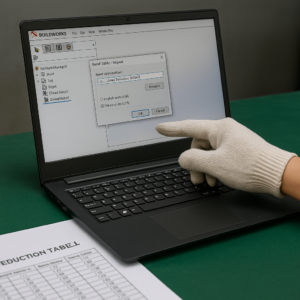
How to Use Bend Table in SOLIDWORKS
Using a custom SOLIDWORKS bend table is straightforward:
- Locate the File Directory: In SOLIDWORKS, navigate to
System Options > File Locations. From the dropdown menu, selectSheet Metal Gauge Table. - Place the Table: Copy the downloaded Excel or
.btlfile into this designated folder. - Apply to Your Part: Open your sheet metal part. In the FeatureManager Design Tree, right-click the
Sheet-Metalfeature and selectEdit Feature. UnderBend Allowance, chooseBend Tableand select the file.
📚 Learn more: How to use bend tables in SOLIDWORKS
How to Apply a Bend Table in Autodesk Inventor
Inventor uses a system of rules to manage sheet metal parameters. To import a bend deduction chart:
- Open the Style Editor: On the
Managetab, clickStyles Editor. - Create a New Rule: In the editor, find
Sheet Metal Unfold Rule. Right-click the default rule and selectNew Style, then give it a descriptive name. - Paste the Table Data: Select your new rule. For the
Unfold Method, chooseBend Table. Copy the data from our Excel file and paste it into the integrated editor. - Activate the Rule: Save the new rule. In your part, go to
Sheet Metal Defaultsand select your new rule from theUnfold Ruledropdown to make it active.
Part 2: The Fundamentals Behind Predictable Bending
Understanding the principles behind bending empowers smarter, more cost-effective design decisions. These calculations form a mathematical model of a complex physical event.
2.1 The Essence of Bending: Stress, Strain, and the Neutral Axis
When a press brake forms metal, it induces stress and strain. The material on the outside of the bend stretches (tension), while the material on the inside shortens (compression).
This duality is why a flat pattern’s length is not a simple sum of its flange dimensions.
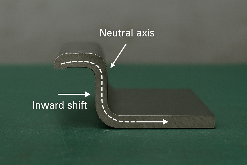
Between these forces lies the neutral axis, a theoretical plane that neither stretches nor compresses. Initially at the material’s center, it shifts inward during bending.
Accurately predicting this neutral axis shift is the core of all flat pattern calculation.
2.2 The Language of Calculation: Key Bending Terms
The industry uses two primary methods to calculate flat patterns. The difference between bend deduction vs bend allowance lies in whether you subtract or add a value to find the flat length.
- Bend Allowance (BA): An additive value representing the arc length of the neutral axis. It is added to the flat leg lengths.
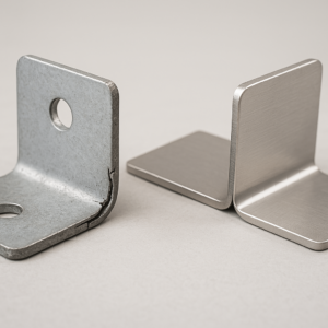
- Bend Deduction (BD): A subtractive value. It is subtracted from the flange lengths when measured to the “virtual sharp” (the theoretical outer corner). This is often more intuitive for external dimension-based parts, like a precision bracket design.
These concepts are linked by the K-Factor, a dimensionless ratio that quantifies the neutral axis location. A correct K-Factor is the cornerstone of accurate sheet metal bending radius vs thickness calculation.
✅ Pro Tip: Want to calculate flat pattern quickly? Try this formula: Flat Length = Leg1 + Leg2 – BD
Part 3: Mastering the Variables That Impact Production
The K-Factor is not static; it is a dynamic variable. Understanding what influences it is key to mastering bending design and ensuring part consistency.
3.1 Variable One: Material Properties
The inherent K-factor material properties dictate how a metal behaves under forming stress.
Ductility and Hardness
A material’s ductility impacts the K-Factor. Softer, more ductile materials like aluminum flow easily, resulting in a higher K-Factor (closer to 0.5).
Harder, less ductile materials like stainless steel resist deformation more strongly. This causes more compression and forces the neutral axis further inward, resulting in a lower K-Factor.
Grain Direction
Sheet metal has a grain direction from the rolling process. Bending “with the grain” is easier but can lead to cracking on sharp bends.
Bending “across the grain” is stronger. For high-reliability parts, especially in automotive sheet metal designs or aerospace prototypes, specifying the bend orientation relative to the grain is key.
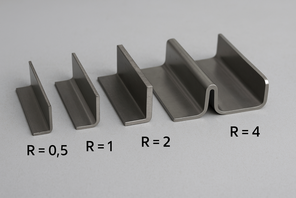
3.2 Variable Two: The Geometry of the Bend
The ratio of the inside bend radius vs thickness (R/T ratio) is a powerful predictor of the K-Factor.
Here’s a reference table based on empirical results:
| Inside Radius (R) | Thickness (T) | R/T Ratio | Typical K-Factor |
|---|---|---|---|
| 1 mm | 1 mm | 1 | 0.33 |
| 2 mm | 1 mm | 2 | 0.42 |
| 3 mm | 1 mm | 3 | 0.45 |
3.3 Variable Three: The Bending Process
The physical method used to form the bend alters the forces on the material. Choosing between air bending vs bottoming vs coining has major implications for precision and repeatability.
- Air Bending: The punch presses the part into a V-die, but it “floats” on three points. The radius depends on the die opening, making the K-Factor variable.
- Bottoming & Coining: These force the material to conform to the tooling shape. Coining sheet metal delivers high consistency and a stable K-Factor but requires dedicated tooling per angle.
Part 4: Advanced Applications for Custom Designs
True mastery comes from adapting data for unique design challenges beyond standard 90° bends.
4.1 Bending Beyond 90°: Calculating for Obtuse Angles
Most tables focus on 90-degree bends. However, you can still use this data to calculate bend deduction over 90 degrees.
By reverse-engineering the K-Factor from known 90° values, you can extend accuracy to obtuse or compound bends—improving the fit of complex folded assemblies.
4.2 The Path to Customization: Creating a Factory-Grade Bend Table
For precision-critical production, a custom table is invaluable. To create a custom bend deduction table, shift from theory to measured data.
Produce test parts using real tools and measure the resulting flange lengths:
BD = (Flange Length 1 + Flange Length 2) - Original Flat Length
This captures your shop’s unique bending fingerprint, aligning your CAD flat patterns with reality.
Part 5: Design for Manufacturability (DFM): A Buyer’s Guide to Reducing Cost and Risk
Even perfect math can’t fix an unmanufacturable design. Smart Design for Manufacturability (DFM) prevents production delays and surprise costs.
5.1 The Fabricator’s Advice: 7 Bending Errors That Impact Your Bottom Line
- Features Too Close to Bends: Use the 4T rule—features should be 4x material thickness from a bend to avoid distortion.
- Ignoring Minimum Flange Length: A flange shorter than 4T + bend radius risks tooling misalignment.
- Forgetting Bend Relief: Add a sheet metal bend relief to corners where tears may form during forming.
- Specifying an Impossible Bend Radius: Avoid radius values below 1T, which may cause cracking.
- Inconsistent Bend Radii: Minimize variation to reduce setup time and tooling cost.
- Bending Collisions: Simulate bending in CAD to catch clearance issues early.
- Using a Generic K-Factor: Repeated again: one-size-fits-all doesn’t apply to bending.
Conclusion: From Flat Pattern to Flawless Partnership
Precision in sheet metal fabrication requires integrating tested data, material behavior, and real-world DFM insight.
This approach transforms guesswork into confidence. For buyers and engineers, it means accurate fit, reduced rework, and predictable delivery.
YISHANG’s approach is grounded in 26 years of fabrication experience across 50+ export markets. We’ve validated our tables through production runs, not just theory.
📌 Need help applying bend data to your next project?
🧩 [Request a Free Design Review Now]
📧 [Contact Us to Start Your Custom Bending Service]
Frequently Asked Questions (FAQ)
Q: What is the difference between bend deduction and bend allowance?
A: Bend deduction is subtracted from the total flange lengths to calculate the flat pattern. Bend allowance is added to each leg to account for the bend arc length.
Q: Can I use the same K-Factor for all materials?
A: No. K-Factor varies based on material ductility, tooling, bend method, and radius-to-thickness ratio.
Q: How accurate are YISHANG’s bend tables?
A: All values are derived from real-world tests performed on our production machines under controlled conditions.
Q: Do you offer assistance with CAD file setup?
A: Yes, our engineering team can review your CAD files and recommend optimal bend values and configurations.
