
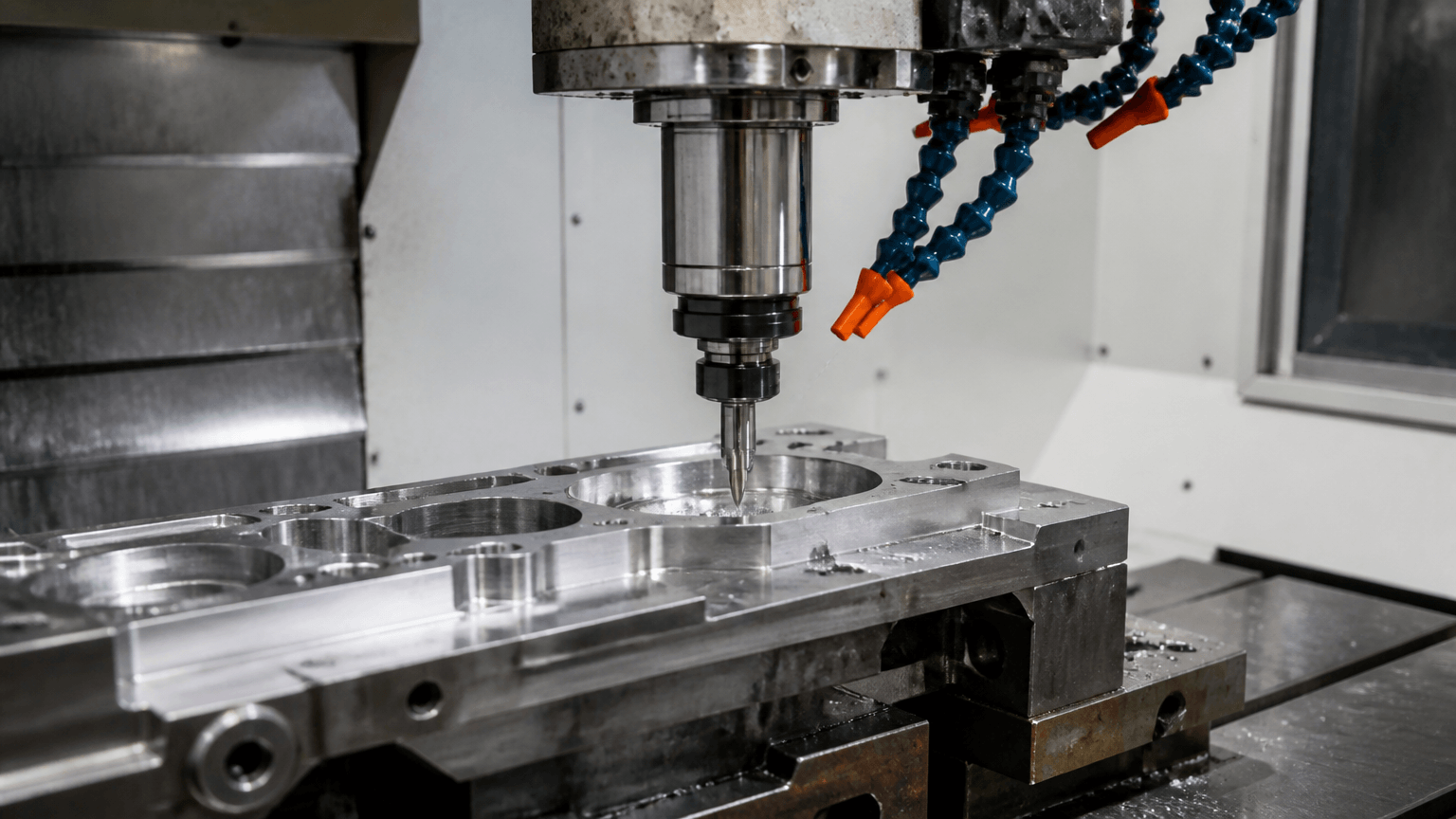
When an OEM drawing calls for a controlled hole pattern, a mating bore, or a contoured metal component, CNC machine uses are about selecting a programmed machining route that can produce those features from suitable stock. A CNC machine uses programmed instructions to control tool movement, spindle rotation or another cutting action, feed rate, and, when supported, auxiliary functions such as coolant and tool changes. The result is not simply a cut blank; it is a machined part whose geometry is created through planned material removal.
That distinction matters when an OEM part could be made from solid stock, cut from sheet, or built as an assembly. CNC machining is primarily subtractive: a cutter removes material from solid or semi-finished stock. By contrast, sheet metal fabrication typically cuts a blank, forms it through bending, and may join separate pieces through welding. A project can use both routes, but the operations, datums, inspection points, and delivery scope should remain clearly defined.
What CNC machines are used for
For an OEM buyer, the practical question is not whether a part can be described as CNC-made. It is whether the selected machine configuration can reach the required features with suitable tooling, workholding, setup access, and inspection. CNC equipment is configured for particular operations, so a milling machine, turning machine, drilling setup, or multi-axis system will not automatically perform every type of work.
Depending on the equipment, the tool or workpiece may rotate, move along controlled paths, and perform several operations without manual repositioning. Common CNC machining uses include:
- machining faces, steps, pockets, slots, ribs, and mounting lands;
- creating drilled, counterbored, countersunk, reamed, or tapped holes;
- producing internal and external bores, bosses, shafts, pins, and concentric diameters;
- forming angled features, controlled transitions, and contoured surfaces; and
- making prototype components, fixtures, replacement parts, and repeat-production components from an approved process.
The machine name alone does not define the usable route. Feature size and location, tool access, material behavior, workholding, setup sequence, and inspection requirements all influence whether the planned operation is practical.
Choose the CNC operation by part geometry
Once the drawing and starting stock are understood, the operation should follow the part geometry. Milling is generally suited to prismatic or contoured work, turning to rotational bodies, and drilling and tapping to defined hole and thread features. Multi-axis machining can help with complex access, but its suitability depends on the actual machine, tooling, workholding, and control plan.
| Operation | Typical geometry and features | Route consideration |
|---|---|---|
| CNC milling | Prismatic parts, flat faces, pockets, slots, steps, angled features, and contoured surfaces. | A rotating cutter removes material from a located workpiece. Tool access and setup count affect handling, cost, and feature-to-feature consistency. |
| CNC turning | Rotational parts such as shafts, pins, bosses, external diameters, grooves, internal bores, and turned threads. | The workpiece rotates around its axis. It suits concentric geometry, while non-rotational mounting patterns may require milling or another operation. |
| Drilling and tapping | Defined hole locations, depths, counterbores, countersinks, and internal threads. | These are often secondary operations on a milling machine or may be performed on drilling equipment. Hole axis, depth, thread specification, chip evacuation, and access matter. |
| Multi-axis machining | Complex contours, features on multiple faces, and orientations that are difficult to reach in one fixed setup. | Coordinated movement can reduce repositioning, but the machine, control, tool length, workholding, and collision-clearance plan must suit the actual part. |
A single component may combine operations. Turning can establish a round body, followed by milling for a keyway or drilling for an off-axis hole. Every additional setup creates another datum-transfer and handling consideration, so reducing setup count is useful only when tool reach, workholding, access, and inspection remain reliable.
Where CNC machining fits in OEM products
For OEM equipment, the machining decision often begins with the interface rather than the outer shape. A component may need to locate, fasten, seal, guide, or support another part, making bores, threads, controlled faces, mounting patterns, or three-dimensional geometry more important than its overall silhouette. Mounting plates, adapter blocks, shafts, pins, machined brackets, fixtures, and tooling components are common examples.
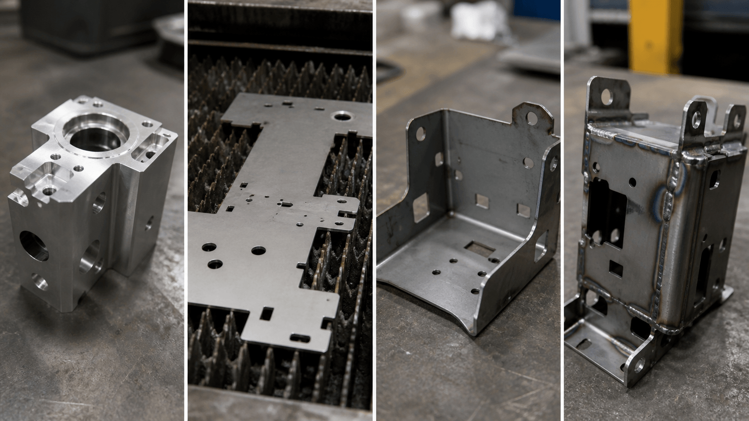
Metal enclosures, housings, brackets, and metal frames often use a mixed manufacturing route. Illustrative scenario: an equipment housing could use laser-cut sheet for its panels, bending for flanges, and welding for the structure. A separate machined insert or mounting interface could then provide a seat for a fastener, connector, bearing, or adjacent assembly. The insert remains a CNC-machined component, while the housing remains a fabricated and welded assembly.
CNC machining is also useful during prototyping when geometry or interfaces may change before release. In repeat production, an approved program, workholding method, tool plan, and inspection approach may be reused when the material and design remain suitable. Revisions, changed quantities, or a different delivery scope can still change the manufacturing route. For a focused overview, see custom CNC machining from first sample to repeat production.
CNC machining or sheet metal fabrication?
There is no universal winner between CNC machining and sheet metal fabrication. Start with the material form, part geometry, required features, estimated quantity, tolerance needs, material utilization, secondary operations, and whether the deliverable is a component or a completed assembly.
| Route | Good initial fit | Points to check |
|---|---|---|
| CNC milling or turning | Solid or semi-finished stock requiring pockets, bores, threads, turned diameters, mounting interfaces, or three-dimensional contours. | Material removal, tool access, workholding, setup count, cycle time, stock utilization, and inspection access. |
| Laser cutting | Flat sheet profiles, openings, slots, and blanks for later forming. See laser cutting when the requirement is mainly a sheet profile. | Material form, edge condition, heat effects, hole requirements, downstream bending, and whether secondary machining is needed. |
| CNC punching | Sheet parts with repeated holes, slots, simple profiles, or formed features suited to available tooling. | Tool availability, feature spacing, edge distance, formed features, marking, material utilization, and the number of operations. |
| Metal bending | Flat blanks that must become channels, flanges, angles, trays, brackets, or enclosure panels. | Bend allowance, springback, bend sequence, tool access, inside radius, hole-to-bend distance, and thin-section distortion. |
| Welding fabrication | Frames, brackets, housings, and assemblies made by joining separate cut or formed components. | Joint design, fit-up, fixturing, weld sequence, distortion, post-weld machining, surface treatment, and assembly inspection. |
| Combined route | A fabricated sheet-metal body with machined interfaces, inserts, spacers, or post-weld features. | Process order, datum transfer, tolerance allocation, weld distortion, assembly access, and responsibility for final inspection. |
Custom sheet metal fabrication built to your drawings can be a better starting point for custom sheet metal parts that are thin, profile-based, or formed into panels, rather than machining the entire shape from solid stock. The reverse also applies: a small machined insert or interface may be appropriate even when the main product is a fabricated assembly. The final route should reflect how the part will be used and delivered, not just how its geometry appears in CAD.
Finishing, assembly, and inspection should be specified separately from the part-making operation. Surface finishing changes the surface condition after cutting, machining, or welding; it does not create the underlying geometry. Assembly joins completed components and may affect access to final features, while inspection verifies dimensions, relationships, appearance, or documentation requirements.
Design inputs that change the machining plan
Manufacturability depends on the relationship between the drawing, material behavior, and process plan. Hardness, machinability, cutting behavior, heat generation, and tool wear can change tool selection and the number of operations. Stainless steel and aluminum fabrication also require attention to grade, stock condition, clamping, and geometry rather than treating the materials as interchangeable.
| Specification area | Information that supports route planning |
|---|---|
| Material and stock | Material grade, hardness or condition, starting form, thickness or diameter, and any material documentation requirement. |
| Geometry and support | Thin walls, deep pockets, unsupported ribs, internal corners, residual stress, clamping surfaces, and features that may deform during cutting. |
| Functional definition | Datums, critical dimensions, geometric tolerances, thread type and depth, mating features, surface requirements, and areas that must remain free of marks. |
| Production and delivery scope | Estimated prototype and production quantities, finish, secondary operations, inspection records, packaging, and whether the requirement is a machined component, fabricated part, welded assembly, or finished assembly. |
Thin walls and unsupported features can move under cutting or clamping forces. Residual stress in stock can also be released as material is removed, while deep pockets may limit tool reach. Complex access may require another orientation or setup, increasing programming effort, workholding requirements, tool wear, cycle time, and inspection burden.
For an RFQ review, provide the complete 2D drawing and 3D CAD model where available instead of relying on a verbal description. Also identify the material grade, starting stock condition, critical features, finish, quantity, inspection documentation, and required delivery scope.
From CAD definition to an inspected CNC part
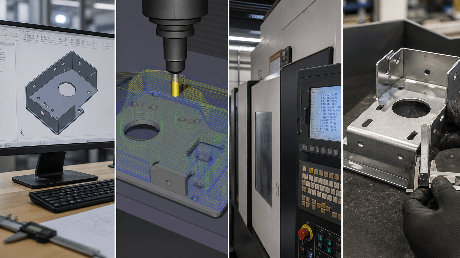
A controlled CNC operation begins with several linked decisions, not just the cutting cycle. The digital model, manufacturing plan, setup, program, and inspection method must all refer to the same part definition.
- CAD and drawing review: The model defines nominal geometry, while the drawing identifies material, datums, functional dimensions, threads, finishes, and inspection requirements.
- CAM planning: The programmer selects operations, tools, cutting approaches, workholding, and setup sequence, then generates toolpaths from the approved design.
- Post-processing: A post-processor converts the toolpath into an NC program suited to the target control system. Not every program is manually written line by line in G-code.
- Setup verification: The workpiece is located, work offsets are established, and tools are measured or referenced. The program may be simulated or reviewed for access and collision risks before cutting.
- First-part and process inspection: When required by the project, the first part is checked against the drawing. Subsequent checks use appropriate calibrated measuring equipment; a CMM may be selected when feature complexity or tolerance relationships justify it.
Inspection planning may also define records, traceability, customer-specific requirements, and nonconformance handling. These controls connect the digital program to a repeatable manufacturing decision. Review quality-control considerations when defining the documentation and inspection scope.
Frequently Asked Questions
OEM teams often encounter the same process questions when a drawing includes both machined features and fabricated sheet-metal elements. The answers depend on the part form, feature access, material, and required delivery scope.
What is the difference between a CNC machine and a CNC cutting machine?
CNC describes the programmed control method, not one specific cutting technology. A CNC cutting machine may use a laser, punch, or another cutting tool to create sheet or plate profiles. A CNC mill or lathe uses controlled tool movement to create features such as pockets, bores, turned diameters, and threads.
Are CNC machines used for sheet metal parts?
Yes, but the specific use matters. CNC machining can produce an insert, mounting interface, hole pattern, or post-weld feature for a sheet-metal product. The sheet itself may be cut by laser or punching, formed by bending, and joined by welding. Machining the entire part may be unsuitable when the design is mainly a thin profile or bent panel.
Is CNC milling or CNC turning better for a metal part with holes and curved features?
Consider turning when the main body is rotational and the holes or bores share its axis. Consider milling for non-round profiles, pockets, slots, mounting patterns, and curved surfaces across a face. A combined route may suit a part with concentric turned geometry and off-axis features.
What information should an OEM provide when requesting a CNC machining or fabricated-metal quotation?
Provide a 2D drawing or 3D CAD file, material grade and thickness or starting-stock condition, critical dimensions, tolerances, datums, threads, surface requirements, estimated prototype and production quantities, and delivery scope. State whether the requirement is a machined component, fabricated part, welded assembly, finish, inspection documentation, or final assembly.
If you are evaluating the route for an OEM part, submit the 2D drawing or 3D CAD file, material grade and thickness or starting-stock condition, critical dimensions, tolerances, datums, threads, surface requirements, estimated prototype and production quantities, and required delivery scope. A technical project review can then compare CNC machining, laser cutting, CNC punching, bending, welding, or a combined sheet-metal process. The review should establish the appropriate manufacturing route without assuming a specific price, lead time, tolerance, or capability before the part information is assessed.