
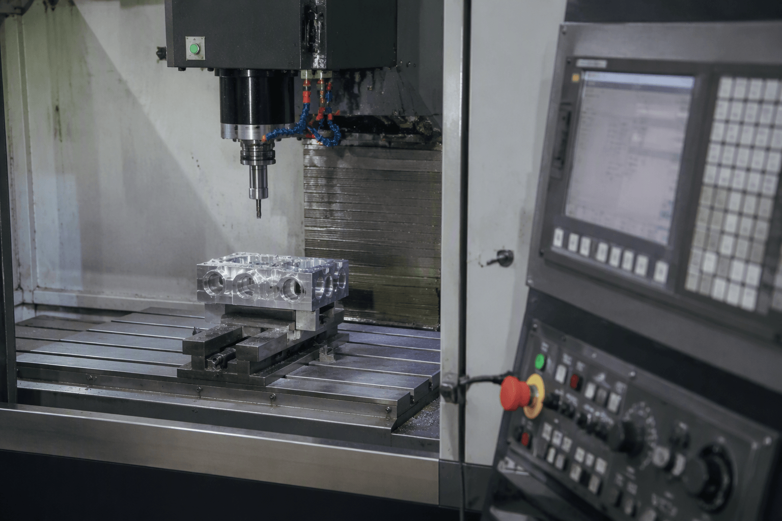
CNC machining technology is a subtractive manufacturing system in which Computer Numerical Control automates the movements and functions of a machine tool. CNC describes the control method, while CNC machining specifically refers to removing material with controlled cutting tools to create the required part geometry.
The complete process connects CAD design data, CAM-generated toolpaths, machine code, a CNC controller, tooling, workholding, material removal, and inspection. Automation improves control and consistency, but engineers and operators are still responsible for programming, setup, verification, monitoring, and quality decisions.
How CNC Control Connects the Machine, Code, and Controller
CNC stands for Computer Numerical Control. Instead of relying only on an operator to move a tool manually, a CNC system follows numerical instructions that define positions, directions, speeds, feeds, and machine functions. The controller interprets these instructions and sends commands to the machine’s motors, spindle, tool-changing system, coolant system, and other supported components.
The controller and the physical machine have different roles. Machine code tells the system what to do; the controller processes those instructions; and the machine converts them into mechanical motion. The achievable result also depends on machine condition, axis configuration, tooling, workholding, material behavior, temperature, and inspection—not programming alone.
Not every CNC-controlled machine performs the same manufacturing process. A CNC mill, lathe, laser cutter, grinder, router, and plasma cutter may all use computer control, but they apply different tools and physical mechanisms. A 3D printer also follows digital instructions, yet it builds material layer by layer instead of removing chips and is therefore an additive process.
How a CAD Design Becomes a Machined Part
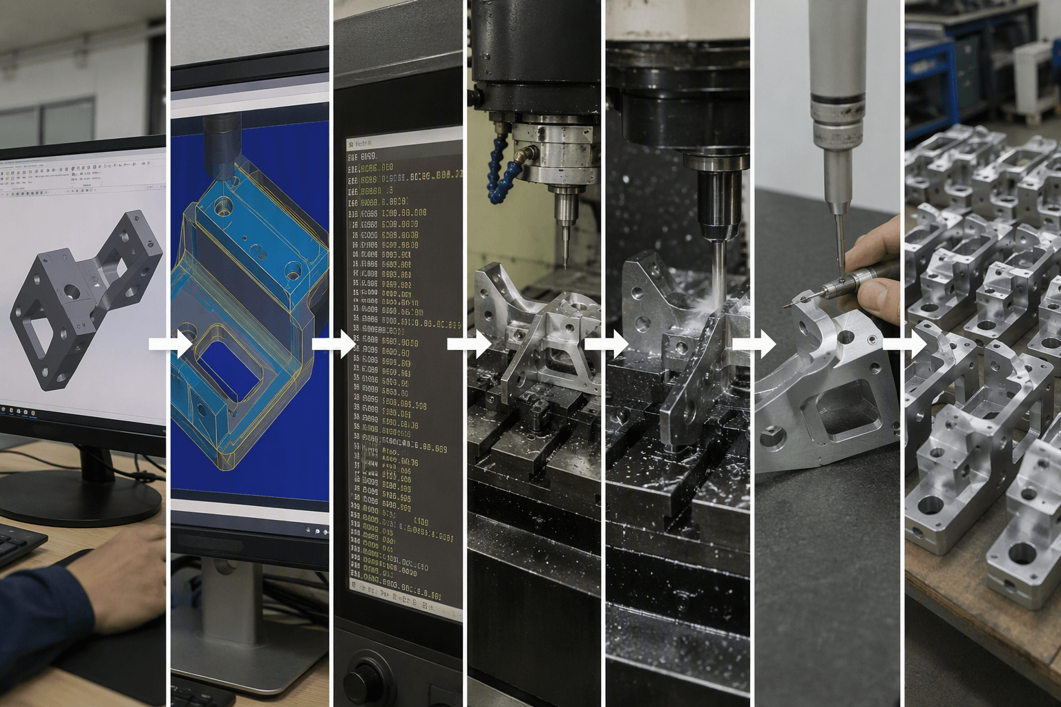
The digital-to-physical workflow contains several connected engineering and production stages. Skipping design review or setup verification can create problems even when the program itself is syntactically correct.
- Review the design data. The team examines the CAD model and dimensioned drawing to identify material, stock form, datums, critical dimensions, surface requirements, threads, hole details, and features that may be difficult to access. Conflicts between the model and drawing should be resolved before programming.
- Select the machining strategy. Part shape determines whether milling, turning, drilling, or a sequence of operations is appropriate. The planner also considers workholding, setup orientation, tool access, part rigidity, inspection access, and any finishing or assembly steps that follow machining.
- Create toolpaths in CAM software. CAM software uses the part geometry, cutting tools, stock definition, and machining parameters to calculate tool movement. A programmer chooses operations such as facing, roughing, pocketing, contouring, turning, drilling, or finishing rather than asking the software to make all manufacturing decisions automatically.
- Post-process the program. A post-processor converts toolpath data into code suitable for a particular machine and controller configuration. G-code generally covers programmed movements and machining modes, including coordinate moves, feed behavior, and positioning. M-code generally controls auxiliary functions such as spindle actions, coolant commands, program stops, or tool-change sequences. Exact codes and supported functions can vary by controller, so examples should not be treated as universal.
- Simulate and verify. Toolpath simulation can reveal collisions, excess travel, remaining stock, or an incorrect machining sequence. It does not replace physical setup checks. The operator must still confirm the program version, tool offsets, work coordinate system, clamps, clearances, and stock orientation.
- Set up and machine the first piece. The workpiece is located and clamped, tools are installed and measured, and offsets are entered. The initial cycle may be approached cautiously so that unexpected motion, vibration, chip accumulation, or interference can be detected.
- Inspect before repeat production. First-piece inspection compares the manufactured component with the approved drawing and other applicable requirements. If results are unacceptable, the team may adjust offsets, tooling, parameters, workholding, or the program. Repeat production begins only after the setup and output have been verified.
Match the Part Feature to the CNC Process
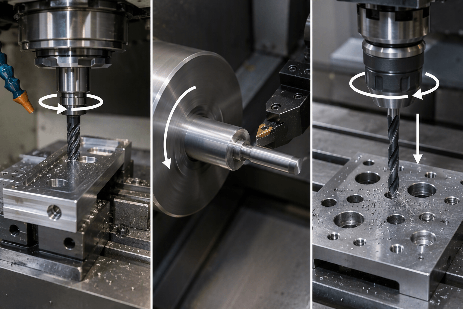
Milling, turning, and drilling are related chip-making processes, but their cutting motions and suitable geometries differ. A component may require more than one operation or setup.
| Process | What rotates? | Typical feature fit | Main considerations |
|---|---|---|---|
| CNC milling | The cutting tool rotates while the workpiece is secured. | Flat faces, pockets, slots, contours, bosses, and prismatic features. | Tool access, setup orientation, internal corner radii, feature depth, and workpiece rigidity. |
| CNC turning | The workpiece rotates while a controlled tool removes material. | Cylindrical diameters, shoulders, grooves, tapers, bores, and external or internal threads. | Part length, diameter relationships, clamping, runout control, and the stability of slender sections. |
| CNC drilling | A drill or related hole-making tool advances along its axis; depending on the machine, the tool or workpiece may rotate. | Through holes, blind holes, and starting features for subsequent boring, reaming, tapping, or countersinking. | Hole depth, diameter, position, chip evacuation, breakthrough condition, and required hole finish. |
| Laser or plasma cutting | No conventional rotating cutting tool is required. | Two-dimensional profiles cut mainly from sheet or plate. | Material and thickness, cut-edge condition, heat effects, kerf, and the need for later bending or machining. |
| Additive manufacturing | Process-dependent; material is deposited, fused, or cured rather than cut away. | Complex prototypes, internal passages, consolidated forms, and geometries that may be difficult to machine. | Material properties, build orientation, support structures, surface condition, dimensional needs, and post-processing. |
On a mill, the secured workpiece may move relative to a rotating cutter through the machine’s available axes. On a lathe, rotation naturally suits geometry organized around a central axis. Drilling may be performed on several machine types, but it remains a specific hole-making operation rather than a synonym for milling.
Some equipment combines turning and milling functions so that multiple features can be produced with fewer transfers. This can reduce handling for suitable parts, but it does not mean all CNC machines have combined capabilities. Routing and grinding are also specialized subtractive processes: routing is commonly associated with high-speed cutting of suitable sheet or panel materials, while grinding uses abrasive action for particular dimensional or surface requirements.
What Controls Accuracy, Tool Life, Cycle Time, and Surface Condition?
Material and stock form. Metals, plastics, and other machinable materials respond differently to cutting. Strength, hardness, ductility, thermal conductivity, abrasiveness, and chip formation affect tool selection and machining parameters. Cast, forged, extruded, rolled, or pre-machined stock may also contain different allowances, stresses, and surface conditions.
Geometry and rigidity. Deep cavities, narrow slots, small internal radii, thin walls, long projections, and high length-to-diameter ratios can limit tool access or allow deflection. A dimension that is straightforward on a rigid, accessible feature may be more difficult to control on a thin or interrupted section. Designs should therefore be assessed in relation to material, feature size, tool reach, and clamping forces.
Cutting tools and axis movement. Tool material, coating, geometry, diameter, and projection influence cutting performance. Axis configuration determines the directions and angles from which features can be reached. More simultaneous movement may improve access for certain shapes, but process stability and verification remain necessary.
Workholding and datums. A vise, chuck, fixture, collet, or other holding method must locate the stock consistently and resist cutting forces without distorting the part. Datum selection connects the drawing to the physical setup. Re-clamping can introduce variation, so setup planning should consider which critical features need to be produced from a common reference.
Feeds, speeds, and coolant. Spindle speed, cutting speed, feed rate, and depth of cut must suit the material, operation, tool, engagement, and machine. Parameters that are too aggressive can accelerate wear, vibration, or deflection; overly conservative settings can increase rubbing and cycle time. Coolant or other cutting-fluid strategies may help with heat, lubrication, and chip evacuation, but their use depends on the material, tool, machine, and operation.
Machine, environment, and inspection. Machine condition, thermal behavior, spindle performance, alignment, setup stability, and tool wear all influence results. Inspection methods must suit the dimension and specification being checked. Operators monitor tool condition, sound, vibration, chips, coolant flow, offsets, and measured output before, during, and after automated cycles.
Choosing CNC Machining or a Different Manufacturing Route
CNC machining is often appropriate when a part requires defined three-dimensional surfaces, controlled interfaces, threads, bores, pockets, or other features produced by material removal. It can support prototypes and repeat production, but it is not automatically the fastest or lowest-cost choice for every component. Material price, removed stock, programming, fixtures, setup count, tool access, inspection, and quantity all affect the production route.
Additive manufacturing builds a part rather than cutting it from stock. It can be useful for complex forms, rapid design evaluation, or geometries with internal features, while machining may offer a more direct path for many engineering materials and functional interfaces. Some additive parts still need machining on sealing faces, holes, or assembly datums. Buyers evaluating early prototypes can also review the 3D printing prototyping path as a distinct option rather than treating it as CNC machining.
Laser and plasma cutting primarily create profiles from sheet or plate. These processes may be followed by bending, welding, machining, finishing, and assembly to make a completed metal product. Conventional CNC machining is more suitable when the design needs features such as accurate bores, milled pockets, bearing seats, or turned diameters that a profile-cutting process does not create by itself.
Production volume changes the decision as well. A one-off repair or simple adjustment may sometimes suit manual machining because CNC programming and setup would add unnecessary preparation. For repeat quantities or complex toolpaths, a verified CNC process can make controlled repetition more practical. The final choice should consider material, geometry, dimensions, precision, surface requirements, quantity, lead-time priorities, and downstream assembly or finishing needs together.
To move from general process knowledge to a focused manufacturing review, visit the custom CNC machining service page. Prepare a CAD model or dimensioned drawing and identify the material, critical dimensions, required quantity, surface requirements, and intended part function. This information helps determine whether machining fits the component and which technical questions need to be resolved next.
Frequently Asked Questions
What is the difference between CNC, CAD, CAM, and G-code?
CNC is the computer-based control of machine movement and functions. CAD defines the component’s geometry and design information. CAM uses that design data to plan operations and create toolpaths. A post-processor then converts the toolpaths into machine-appropriate code. G-code generally describes movements and machining modes, while auxiliary commands are commonly handled through M-code.
Does a CNC machine run without an operator after programming?
A CNC machine can execute an automatic cycle, but programming does not eliminate operator or engineering involvement. People must select tools, secure the workpiece, establish coordinates, verify offsets, check clearances, inspect the first piece, monitor tool wear, and respond to process changes or alarms.
Is a 3D printer a CNC machine or a different manufacturing process?
A 3D printer is digitally controlled, but it is normally classified as additive manufacturing because it builds parts layer by layer. CNC milling and turning are subtractive processes that remove material. The technologies can complement each other, but they are not interchangeable categories.
What is the main difference between CNC milling and CNC turning?
In CNC milling, a rotating cutting tool moves relative to a secured workpiece, making it suitable for many prismatic features. In CNC turning, the workpiece rotates while the cutting tool is controlled along it, making the process a natural fit for cylindrical geometry. Some parts require both operations.