
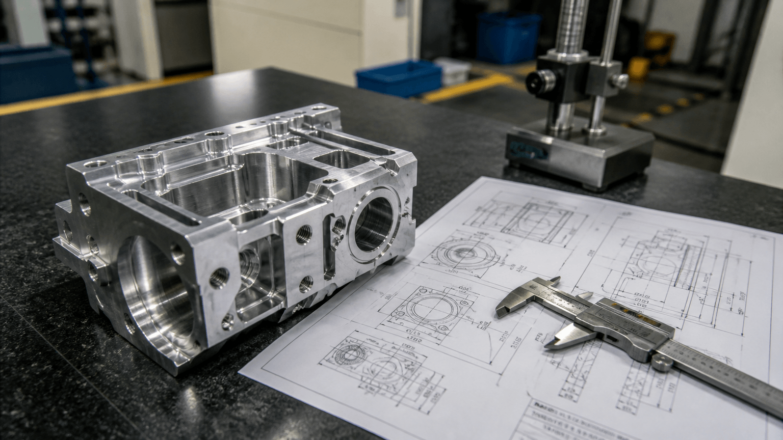
Custom CNC machining is a subtractive manufacturing process that uses programmed cutting operations, commonly milling or turning, to create controlled features from solid stock or a near-net blank. Unlike CNC punching and laser cutting, which primarily create holes and profiles in sheet, machining can produce pockets, bores, threads, precision interfaces, and three-dimensional surfaces. The right route depends on the part geometry, material, quantity, tolerances, finish, and role within the final assembly.
For an OEM buyer, the practical question is not simply whether a part can be machined. It is whether machining is the most appropriate way to produce the required features without adding unnecessary stock removal, setups, or inspection work. Some components clearly suit machining, while others are better fabricated from sheet or produced through a hybrid route.
Where Custom CNC Machining Fits
When a component must locate, support, seal, or align other parts, CNC milling may provide the controlled faces and features the assembly requires. The process removes material with rotating cutters while the workpiece is held in a defined position. It is commonly considered for prismatic components such as mounting blocks, equipment brackets, tooling plates, housings, heat-transfer components, and parts with machined pockets or mating faces.
CNC turning is another subtractive route, used primarily for rotational geometry such as shafts, pins, spacers, bushes, and threaded cylindrical components. A turned part may be installed in a sheet metal assembly, but turning itself is not sheet metal fabrication.
Machining becomes a strong candidate when a design contains meaningful thickness changes, accurate relationships between several faces, recessed features, controlled bores, or interfaces that locate another component. However, it is not automatically the best process for every metal part. A broad, constant-thickness panel may be produced more efficiently by laser cutting or punching followed by bending, while a long component with a consistent cross-section may suit extrusion with secondary machining.
Buyers evaluating this route can review the custom CNC machining service path. Process selection should still begin with the geometry and functional requirements, rather than the process name shown on an earlier drawing or quotation.
CNC Machining, Sheet Metal Fabrication, or a Hybrid Route?
Choosing the wrong starting process can create avoidable machining, joining, or finishing work later in the project. The processes below are related through the finished product, not because they perform the same manufacturing task. This matrix provides an initial comparison; final feasibility depends on the specified material, dimensions, quantity, tolerances, appearance requirements, and available supplier capability.
| Route | Starting input | Geometry it creates efficiently | Important considerations |
|---|---|---|---|
| CNC milling or turning | Solid stock or near-net blank | Pockets, bores, threads, stepped faces, rotational parts, and controlled mating features | Tool access, workholding, setup count, material removal, and inspection |
| CNC punching | Sheet | Repeated holes, slots, knockouts, and sheet profiles made with punch tooling | Tool availability, edge condition, feature spacing, and possible forming operations |
| Laser cutting | Sheet, plate, or another supported stock form | Two-dimensional profiles and cutouts without dedicated profile tooling | Cut edge, heat effects, nesting, and downstream bending or machining |
| Bending and welding fabrication | Cut sheet, plate, or tube | Panels, frames, covers, enclosures, and welded structures | Bend access, springback, joint design, distortion, and finishing |
| Casting | Material formed in a mold | Complex near-net shapes and integrated features | Tooling, quantity, draft, shrinkage, and secondary machining |
| Extrusion | Material pushed through a die | Long parts with a constant cross-section | Die requirements, section design, cut length, and secondary features |
| Additive manufacturing | Material built layer by layer | Complex internal paths, consolidated shapes, and development parts | Material properties, surface condition, support strategy, and post-processing |
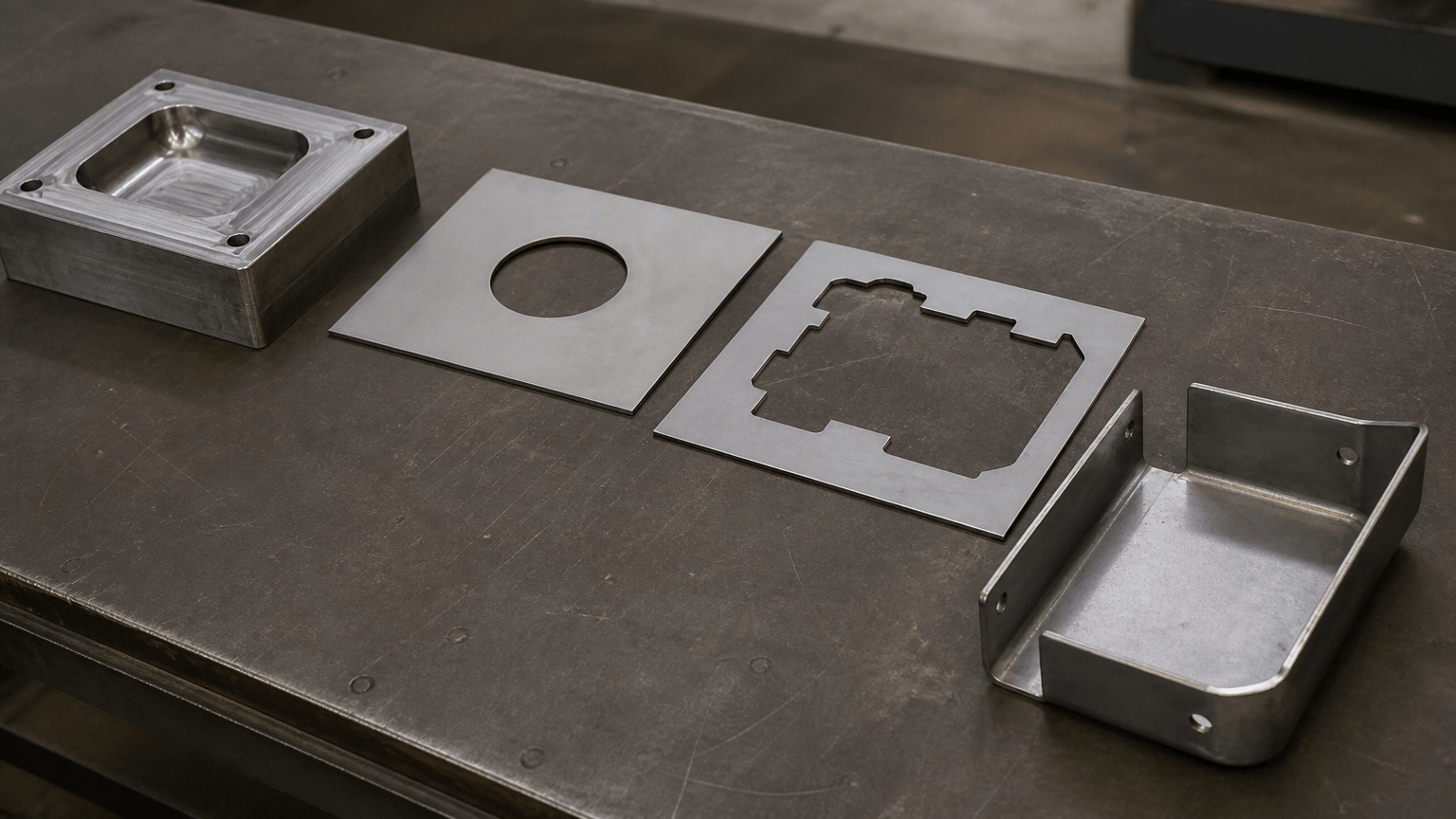
A hybrid route is often appropriate for industrial equipment. For example, a metal enclosure could use laser-cut and bent panels for its outer structure, welded brackets for support, and machined inserts for bearing, connector, or alignment interfaces. This approach avoids machining the entire enclosure from solid stock while retaining controlled features where they provide functional value. Designs dominated by panels, frames, and weldments should also be assessed through a sheet metal fabrication review.
Feature-Level DFM for Machined Parts
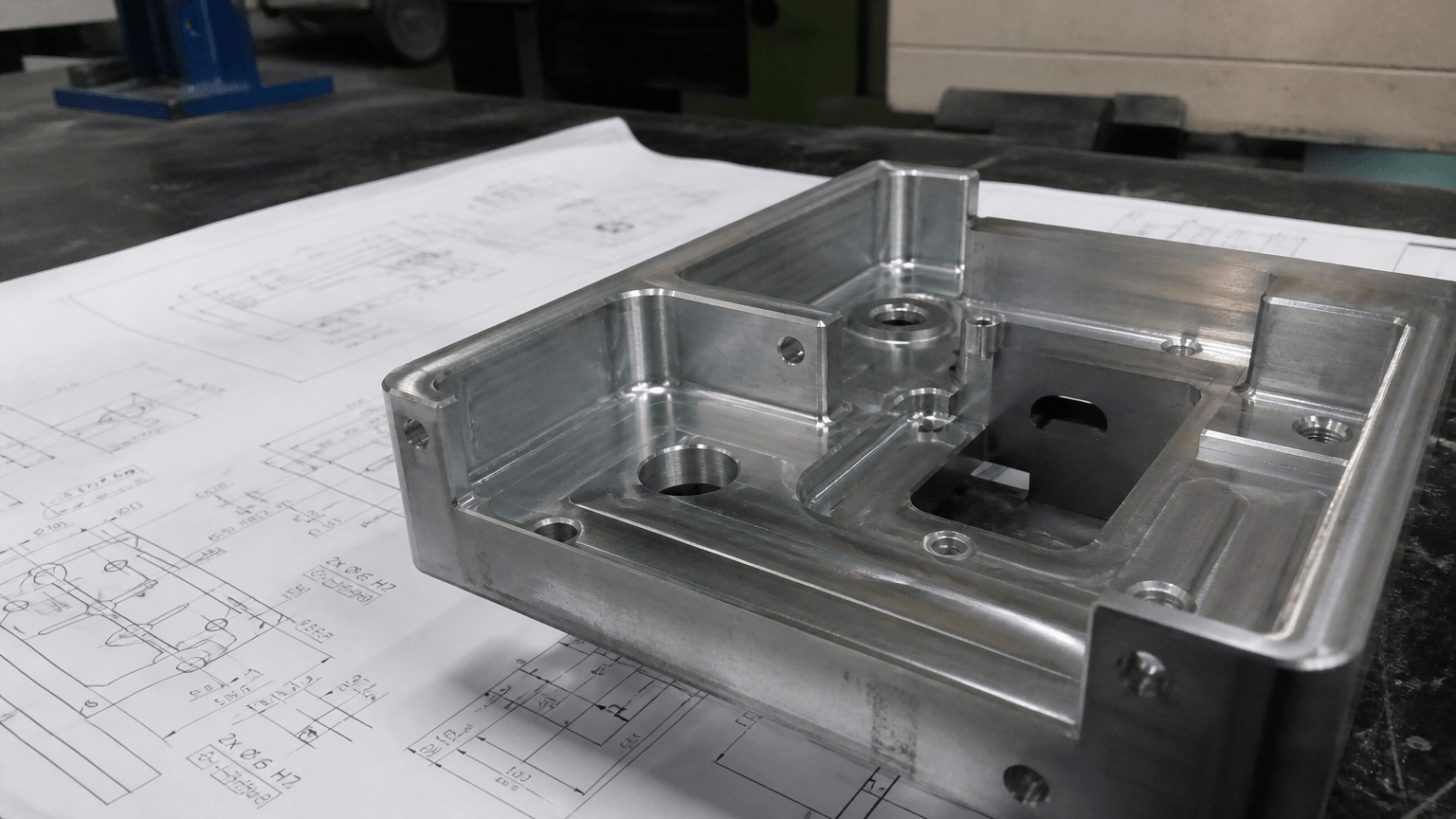
A CAD model can appear complete while leaving questions that affect programming, workholding, tool selection, and quotation. Those issues often become visible only when each feature is considered in relation to cutter access, clamping surfaces, and the order of operations. The following features should therefore be reviewed before fixture planning or production begins.
- Internal corners: A rotating cutter naturally leaves a radius in an internal corner. A perfectly sharp corner may require another process, a relief feature, or a change to the mating component. Allowing a larger radius may also permit a more rigid tool and easier access.
- Deep pockets and narrow slots: Tool access becomes more difficult as a feature becomes deeper and narrower. Long tool projection can reduce rigidity and affect the cutting strategy, machining time, and achievable result. Pocket depth, corner radius, opening width, and access direction should be reviewed together.
- Thin walls: Cutting forces and residual material stress can cause a slender wall to move during or after machining. Material, wall height, surrounding support, and machining sequence all matter, so a universal minimum wall value would be misleading.
- Workholding and multiple faces: The supplier needs stable clamping surfaces that do not damage critical areas. Features distributed across several orientations may require additional setups or dedicated fixtures. A final operation can become difficult if earlier machining removes every convenient clamping surface.
- Holes and threads: Define the hole diameter and depth, whether it is through or blind, the thread designation, the required engagement, and the available access. Intersecting holes, angled holes, deep threads, and threads close to edges may require specific review.
- Undercuts and inaccessible features: A feature hidden behind another wall may not be reachable through a standard machining approach. Explain its function so the supplier can assess alternate tooling, split construction, or a design change.
- Edges and deburring: State whether an edge needs basic burr removal, a controlled chamfer, a radius, or protection as a sealing or appearance surface. The general instruction “break all edges” may not define a measurable requirement.
- Finishing allowance: Anodizing, powder coating, polishing, plating, or another finish can alter appearance and may affect dimensions or fits. Confirm the material-finish combination and any masking requirements with the supplier.
A contextual DFM review is particularly useful when pockets, threads, thin walls, and mating surfaces interact. Capability-dependent features should be assessed from the actual model and drawing instead of applying generic online limits developed for a different material or geometry.
Specify Tolerances Through Function, Datums, and Inspection
When every dimension receives the same tight tolerance, the drawing may obscure which features actually control fit and assembly. Linear size, hole diameter, hole position, flatness, perpendicularity, and surface profile address different aspects of a part. The drawing should identify the characteristics that affect sealing, movement, alignment, safety, or assembly, while allowing practical variation elsewhere.
For illustration only, a dimension of 20.00 mm ±0.05 mm permits values from 19.95 mm to 20.05 mm, creating a total tolerance zone of 0.10 mm. This example explains bilateral tolerance; it is not a statement of Yishang’s capability. A hole-size tolerance also does not automatically control the position of that hole relative to a mounting datum.
Choose datums that reflect how the component is located in the finished product. A primary mounting face, locating bore, or functional edge may provide a more useful reference than an arbitrary outside surface. The datum scheme must also be physically accessible during manufacturing and measurement.
Inspection expectations require similar clarity. Buyers should identify critical characteristics, sampling expectations, measurement conditions, and required documentation rather than requesting only “full inspection.” Part size, material behavior, setup changes, surface finish, temperature, feature accessibility, and the selected measurement method can affect how a result is produced and interpreted. Supplier-specific inspection methods and report formats should be confirmed during project review; general information is available on Yishang’s quality control page.
What Drives CNC Machining Cost and Scheduling?
Two parts with similar outside dimensions may require substantially different amounts of programming, setup, cutting, and inspection. Buyers comparing quotations need to consider the complete production route, not stock size alone. A meaningful quotation distinguishes one-time preparation from recurring unit work and reflects the features that drive manufacturing effort.
| Cost or schedule driver | Why it matters | Useful buyer input |
|---|---|---|
| Raw material and stock form | Availability, stock size, required certification, and removed volume influence purchasing and machining | Material specification and acceptable alternatives, if any |
| Programming and process planning | Complex toolpaths and operation sequencing require preparation before cutting | Clean 3D model and controlled drawing |
| Fixtures and setups | Additional orientations require handling, alignment, and sometimes dedicated workholding | Functional datums and expected quantity |
| Cycle time and material removal | Deep pockets or a large difference between the stock and final shape may extend cutting time | Permission to simplify hidden or noncritical geometry |
| Tools and feature access | Long-reach, small, or specialized tools can change the machining strategy and tool consumption | Corner radii, feature depths, thread details, and access directions |
| Tolerance and inspection | Critical controls may require more stable processing and additional measurement | Clearly marked critical characteristics and inspection basis |
| Finishing and packaging | External processing, masking, cosmetic handling, and protection add operations | Finish specification, appearance zones, and packaging requirements |
| Quantity | Programming and fixture effort can be distributed across more units, while batch size affects production planning | Prototype, batch, and expected repeat quantities |
Removing unnecessary pocket depth, accepting practical internal radii, reducing avoidable setup changes, and limiting tight controls to functional features may improve manufacturability. The effect remains project-specific, however, and no exact saving or lead-time reduction should be assumed before the complete design is reviewed.
From Prototype to Repeat Production and Final Assembly
A prototype should test the component in its intended assembly, not merely show that the individual part can be machined. This stage can reveal whether mounting holes align, tools can reach fasteners, coatings interfere with fits, cables clear adjacent brackets, and variation in the surrounding sheet metal has been addressed. Findings should be reflected in the controlled production data before repeat orders begin.
When a machined component enters a fabricated assembly, review the complete tolerance chain. A precise insert cannot correct every variation in a welded frame, and a machined bracket may still misalign if its locating scheme relies on an uncontrolled panel edge. Weld sequence, bend variation, fastener clearance, coating buildup, and assembly access should be considered alongside the machined dimensions.
Prototype approval should also be tied to revision control. If the geometry, material, tolerance, finish, or inspection requirements change after sampling, the production release should identify the approved revision and update both the model and drawing. Buyers validating geometry, fit, and assembly before repeat orders can use the prototyping service as the next project stage.
Request a Drawing-Based Process and DFM Review
Submit the 3D model and revision-controlled 2D drawing, along with the material specification or required performance conditions. Include prototype and expected batch quantities, critical dimensions, datums and fits, inspection expectations, finish and appearance requirements, mating-part context, delivery destination, and required project timing. These inputs allow uncertain features and assembly interfaces to be reviewed before the quotation is prepared.
Yishang supports B2B OEM and ODM custom manufacturing. The company has more than 26 years of experience manufacturing custom sheet metal parts and metal products, exports to more than 50 countries, and holds ISO and RoHS certifications. The project review can assess whether the component is better suited to machining, fabrication, or a hybrid route, with capability-dependent details confirmed against the submitted design.
Frequently Asked Questions
Is CNC machining the same as CNC punching or laser cutting?
No. CNC machining removes material from solid stock or a near-net blank using controlled cutting tools. CNC punching uses punch-and-die tooling to create features in sheet, while laser cutting uses a focused beam to cut profiles and openings. All three processes can be numerically controlled, but they use different inputs and tooling principles and are suited to different geometries.
Why should tight tolerances be assigned only to functionally critical features?
Tighter controls can affect process planning, setup stability, cycle time, inspection effort, and scrap risk. Applying them to nonfunctional dimensions may add cost without improving the product. The RFQ drawing should clearly mark the dimensions, geometric controls, datums, and mating relationships that determine fit or performance.
Can CNC machining produce perfectly sharp internal corners?
A conventional rotating cutter leaves an internal radius. If a sharp corner is functionally necessary, the supplier must evaluate another operation, a relief, or a different part design. In some designs, the mating component can be chamfered or the internal radius enlarged without changing function, but that decision should be confirmed during DFM review.
When should an assembly combine machined and fabricated parts?
A hybrid design may be appropriate when panels, covers, frames, or weldments provide the main structure but selected locations require controlled bores, threads, bearing seats, alignment faces, or durable inserts. The prototype and production review should account for bending, welding, fastening, finishing, tolerances, coating buildup, and assembly access at each interface.