
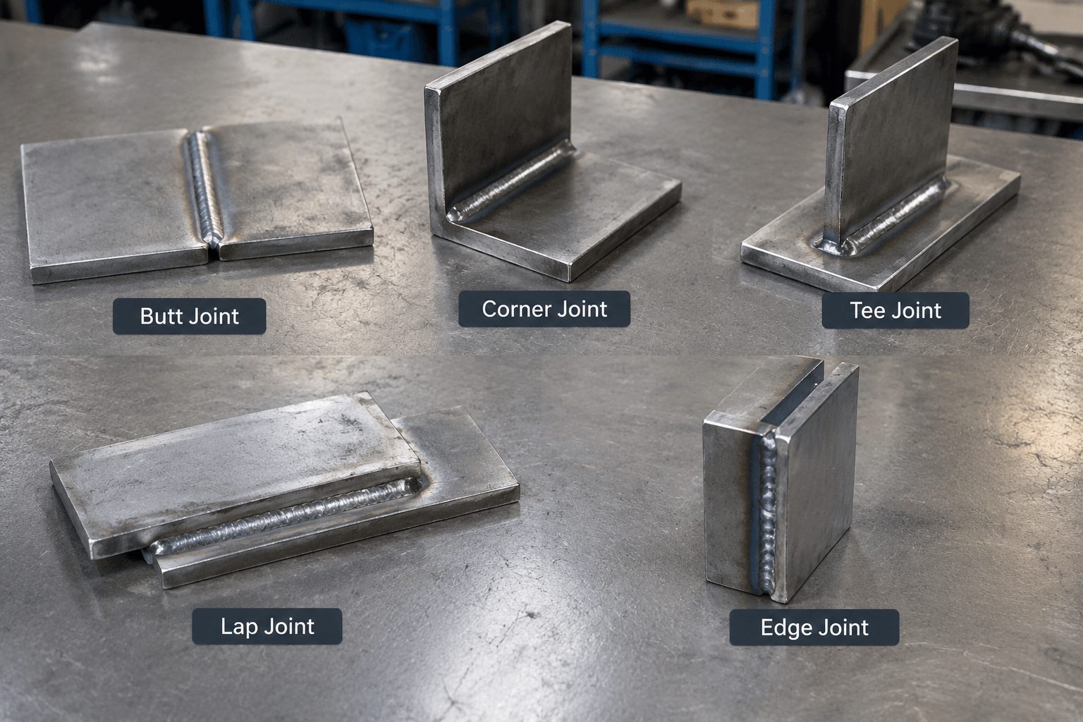
A fillet is not one of the five basic weld joints. A fillet weld is a weld type, while the five basic joint configurations are butt, corner, tee, lap, and edge.
The Five Basic Joint Configurations
A joint configuration identifies the physical arrangement of the parts before the weld is selected or applied. The same general configuration can involve different weld types depending on the material, thickness, access, loading, drawing requirements, and applicable specification.
Two members meet edge to edge in approximately the same plane.
Two members meet at a corner, commonly forming an inside or outside angle.
One member meets the face of another at approximately 90 degrees, forming a T shape.
One member overlaps another, so their surfaces lie over one another.
Two members are placed side by side and joined along adjacent edges.
The labels in this diagram describe geometry only. They do not state that every butt joint receives a butt weld, or that every tee, lap, or corner joint receives a fillet weld. A fabrication drawing may define the required weld form, preparation, size, length, continuity, and inspection requirements for the particular design.
Where a Fillet Weld Fits
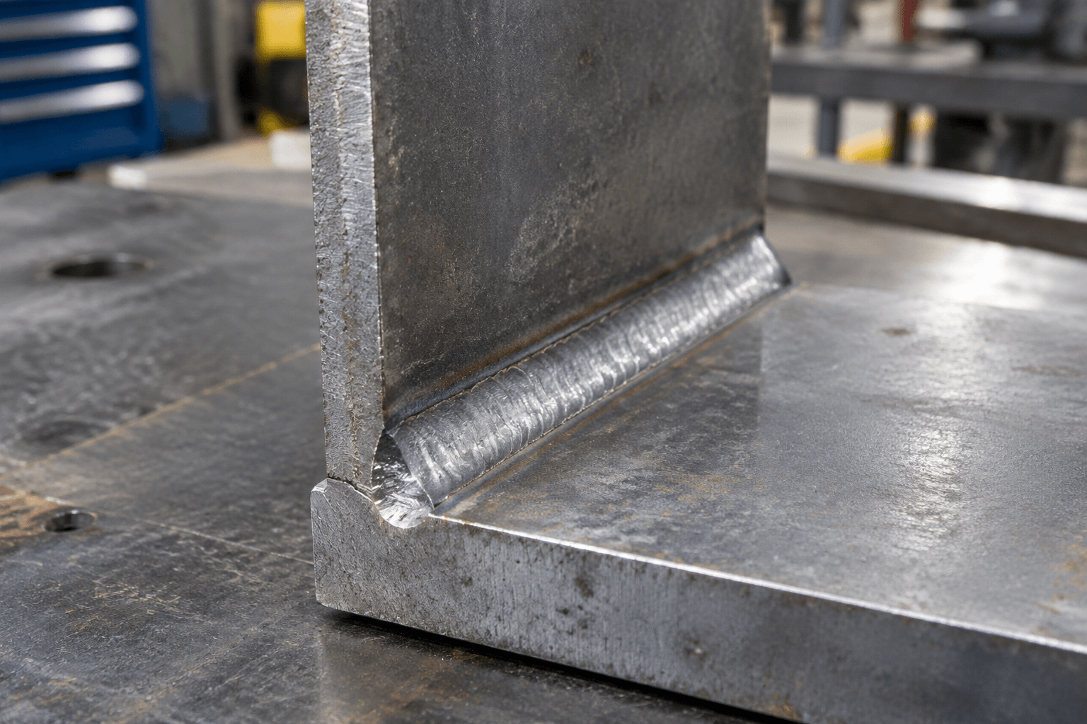
A fillet weld is generally recognized by its approximately triangular cross-section. It is deposited in the angle between two members or surfaces rather than necessarily requiring the members to be aligned edge to edge. This makes the fillet weld relevant to several joint configurations, especially tee, lap, and corner arrangements.
The weld is shown at the intersecting surfaces. The drawing does not indicate a weld dimension or acceptance requirement.
For a tee joint, the weld can be placed where the upright member meets the face of the horizontal member. In a lap joint, a fillet may be placed along the edge of the overlapping member. In a corner joint, a fillet may be deposited along the inside angle. These are typical relationships, not universal rules. A corner, lap, or tee joint can require another weld arrangement when access, load direction, thickness, appearance, sealing, distortion control, or the engineering specification calls for it.
Weld selection therefore follows the joint design rather than the name of the joint alone. Material and thickness can affect preparation and weld details, while geometry and access can affect where the weld can be placed. The applicable drawing or specification should control the actual requirement; a general explanation cannot prescribe a suitable weld size, process, position, inspection acceptance, or edge preparation for every application.
Joint Configuration, Weld Type, and Seam: A Clear Distinction
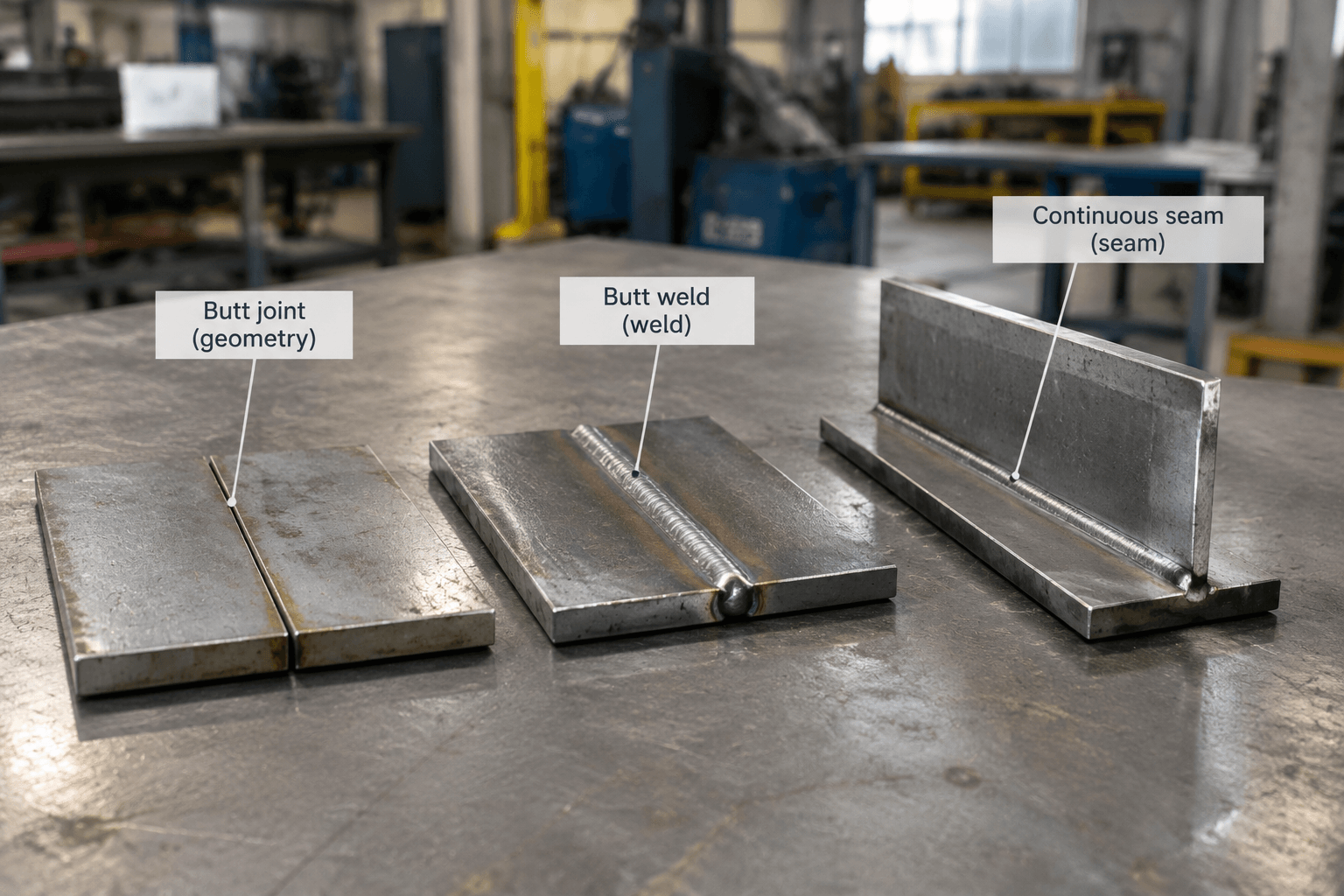
These terms are often mixed because they describe different aspects of the same fabricated assembly. A joint tells you how the parts meet. A weld tells you how material is deposited or how the parts are joined. A seam describes a joined line or continuous seam feature and is not an additional member of the five basic joint configurations.
| Term | What it describes | Simple example |
|---|---|---|
| Joint configuration | The relative arrangement of the members before or at the connection. | A lap joint has one member overlapping another. |
| Weld type | The form or profile of the deposited weld. | A fillet weld is placed in the angle between meeting surfaces. |
| Butt joint | A configuration in which members meet edge to edge in roughly the same plane. | Two sheet edges are aligned and brought together. |
| Butt weld | A weld joining members arranged in a butt-joint configuration. | Weld metal joins the aligned edges; preparation may depend on the design. |
| Seam | A joined line or seam-weld feature, often described by its continuity or location. | A continuous joined line along an enclosure panel. |
A butt joint and a butt weld are consequently related but not interchangeable. The first identifies the part arrangement; the second identifies the weld joining that arrangement. Likewise, “seam” does not replace butt, corner, tee, lap, or edge. It may describe the visible or functional line created by joining, and a seam-weld symbol may communicate a particular drawing requirement, but it is not a sixth basic joint configuration.
How Drawings Communicate the Requirement
Weld symbols are a shorthand used on engineering drawings to communicate weld requirements. A symbol may identify the intended weld type and, depending on the drawing system and notation used, may be accompanied by information about location, length, size, extent, or other requirements. The symbol should be read together with the reference line, arrows, notes, dimensions, material information, and the applicable specification.
Aligned member edges describe the joint configuration.
Weld material joins the members in that configuration.
A joined line or seam feature; not a separate basic configuration.
This distinction matters when reviewing a sheet metal assembly. For example, an enclosure may contain several panel intersections with different configurations, while its drawing uses separate weld symbols or notes for each location. When reviewing a fabricated product such as a custom sheet metal enclosure, first identify how the panels meet, then confirm what the drawing requires at each joint.
For early technical review, the useful sequence is straightforward: identify the part arrangement, identify the specified weld type, then check the drawing notes for dimensions, continuity, preparation, and inspection requirements. This prevents a fillet symbol, a butt-joint description, or a seam note from being treated as though all three describe the same thing.
Frequently Asked Questions
What are the five basic weld joint configurations?
The five basic configurations are butt, corner, tee, lap, and edge. They describe how the members are positioned in relation to one another, not the specific weld deposited at the joint.
Can a fillet weld be used on a lap, tee, or corner joint?
Yes. Fillet welds are commonly placed where surfaces meet in lap, tee, and corner arrangements. However, the actual weld type and details depend on the design, material, access, drawing, and applicable requirements, so those configurations do not automatically require fillet welds.
Is a butt joint the same as a butt weld, and is a seam another basic joint configuration?
No. A butt joint describes aligned members meeting edge to edge, while a butt weld is the weld joining them. A seam describes a joined line or seam feature; it is not an additional basic joint configuration.