
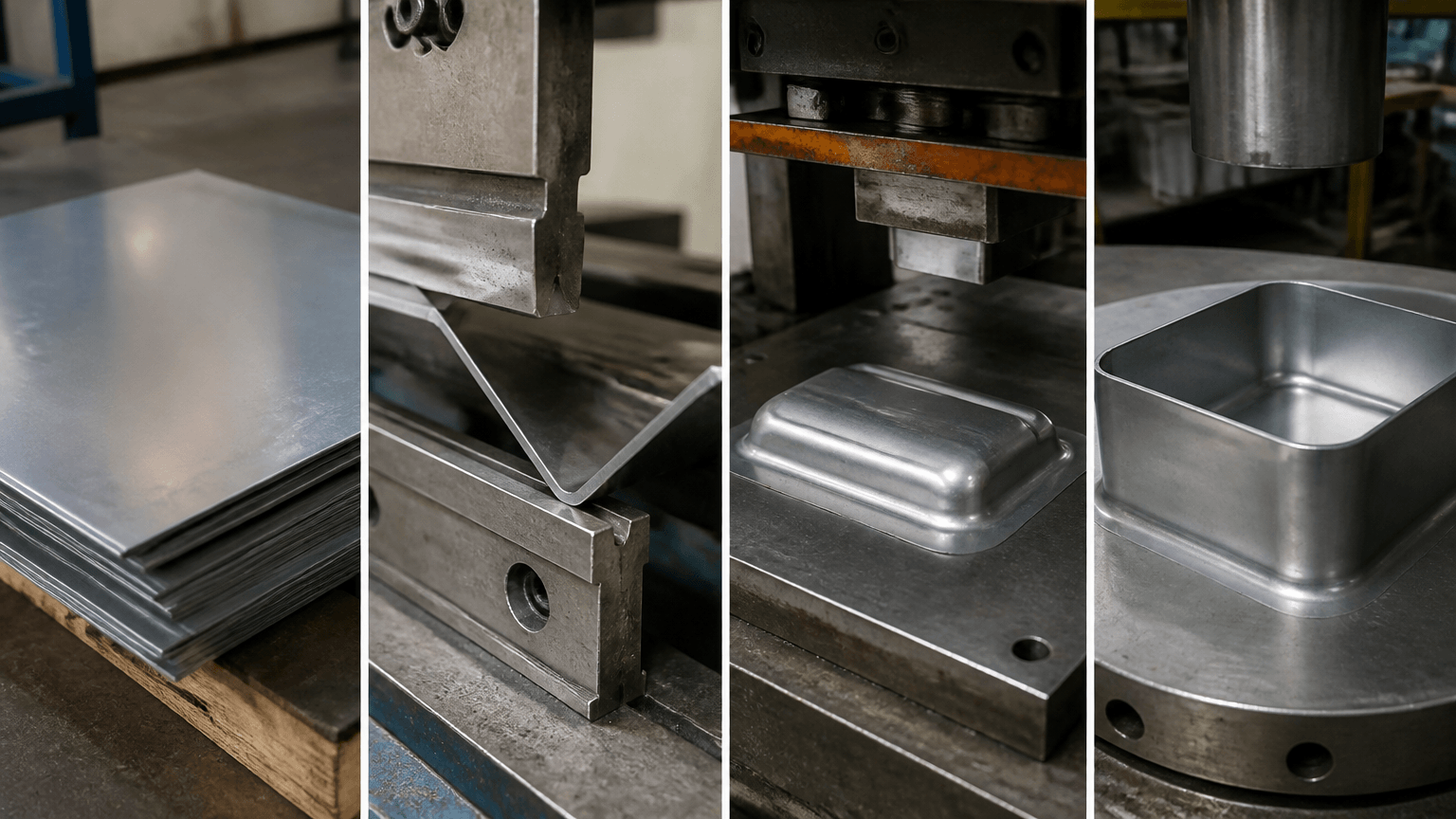
Forming steel sheet means permanently reshaping flat steel through controlled plastic deformation. Press brake bending, stamping, deep drawing, roll forming, and hydroforming are different processes for different geometries and production conditions. For a bracket, enclosure, chassis, panel, or drawn shell, the appropriate route depends on the steel grade and condition, feature geometry, order volume, required accuracy, visible surfaces, tooling commitment, and downstream fabrication.
A buyer may begin with a part that appears to need only several bends, yet deep walls, short flanges, holes near bend lines, cosmetic faces, or inaccessible features can change the manufacturing route. The review must determine which features can be made with discrete bends, which require controlled material flow or dedicated tooling, and which should be cut, joined, machined, or finished in a separate operation.
The Boundary Between Forming and Other Fabrication Work
Process boundaries become important when an RFQ combines cut features, formed geometry, welded interfaces, and finished dimensions. Forming creates bends, flanges, channels, hems, ribs, offsets, or drawn walls by deforming the sheet. Laser cutting and CNC punching primarily create the blank, holes, and slots; machining removes material; welding joins components; and coating, inspection, and assembly remain separate stages.
For example, an equipment enclosure may start as a laser-cut blank, gain mounting flanges and offsets through press brake bending, then receive welds, a finish, inspection, and packaging. A chassis may require holes and slots before forming, while a bracket with a hole close to a bend may need the hole position reviewed after the bend sequence is defined. A deeper box-like shell may not be practical as a set of ordinary bends and could require an evaluation of deep drawing or another route. These are project-specific decisions, not proof that one process suits every part.
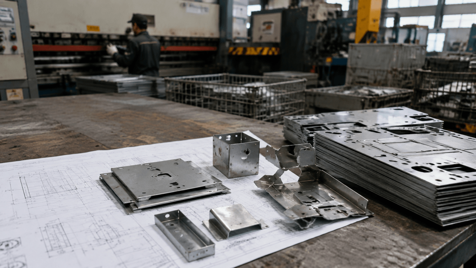
These operations can still belong to one fabrication route. A blank may be laser cut or punched, deburred, formed, fitted with inserts, welded, coated, inspected, assembled, and packaged. The order is not universal. A hole created near a bend may elongate or shift during forming, while adding it afterward requires suitable access and another cutting or machining step. Welding can also change flatness, angles, and hole positions after the forming dimensions have been established.
Comparing the Main Steel-Sheet Forming Processes
Choosing a process before reviewing feature depth, tool access, quantity, and design stability can create avoidable tooling or secondary work. Each method controls the sheet differently, so suitability must be assessed against the drawing, material condition, available equipment, quality requirements, and expected production demand.
| Process | How it forms the sheet | Where it may fit | Questions to resolve |
|---|---|---|---|
| Press brake bending | A punch and die create discrete bends along selected lines, normally through a planned sequence. | Prototypes and varied low- or medium-volume parts with accessible straight bends. | Can every bend be reached? Are the flanges controllable? What radius, sequence, springback compensation, and hole clearance are needed? |
| Stamping or pressing | A dedicated or semi-dedicated die produces repeated formed features. Cutting and piercing may be integrated into the tooling sequence. | Stable recurring parts with bends, ribs, embossments, or other repeated features that may justify tooling. | How will tool development, trials, maintenance, material use, secondary work, and later revisions affect lifecycle cost? |
| Deep drawing | A punch draws a blank into a die cavity while the material flows inward to create substantial depth. | Cup-like, shell-like, or box-like parts that are not practical as a sequence of simple bends. | Are the draw ratio, blank shape, blank holding, lubrication, radii, thinning, wrinkling, cracking, and possible redraw stages workable? |
| Roll forming | Sheet or strip passes through successive rolls that progressively develop the profile. | Long parts with a substantially constant or regularly repeated cross-section. | What profile stability, strip width, end condition, cut-off method, quantity, and dimensional control are required? |
| Hydroforming | Fluid pressure assists in pushing the sheet against a forming surface or tool. | Complex curved shapes when the equipment, tooling approach, cycle, material, and dimensional requirements support it. | Can pressure, sealing, tooling, surface condition, repeatability, and project economics be managed? |
Press brake flexibility does not make bending suitable for every shape. Deep walls, continuous curves, long repeated profiles, or numerous recurring features may favor another process. A stampable shape may still suit bending when quantities are limited or design changes remain likely. See Metal Bending for discrete bend considerations and Deep Drawing for the distinct material-flow issues associated with drawn walls. These comparisons do not establish that every process is available for a particular project.
Material Conditions That Define the Forming Window
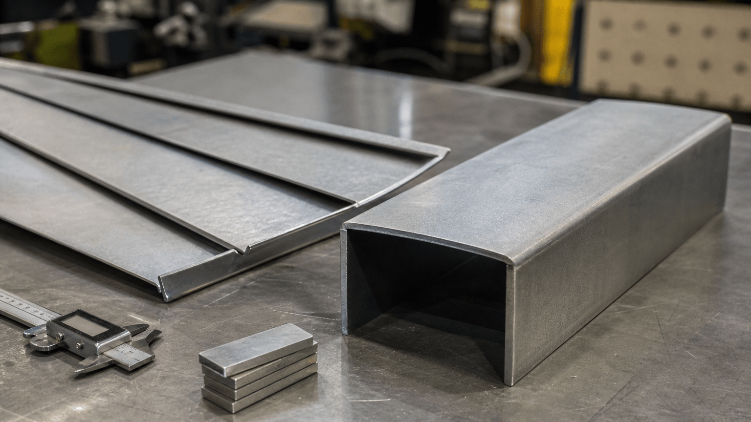
Specifying only steel sheet and a nominal thickness leaves major forming variables unresolved. The exact grade, yield strength, elongation, thickness and permitted variation, rolling direction, edge condition, coating, and surface finish can change the required force, tooling approach, defect risk, and released geometry.
Higher yield strength generally increases forming-force and springback concerns. High-strength steel may require different tooling, a larger radius, or additional compensation compared with a softer grade. Elongation helps describe the material’s ability to accommodate strain, but it does not confirm that a particular bend or drawn feature is feasible.
There is no universal minimum bend radius for steel sheet. The workable radius depends on grade, thickness, material condition, rolling direction, tooling, cut-edge quality, and structural or cosmetic requirements. Bend orientation relative to the rolling direction can affect cracking risk, so any required orientation should be shown on the drawing and considered during blank nesting.
Depending on grade and finish, stainless steel may present greater springback or more visible tool marking. Galvanized, laminated, coated, and prefinished sheets require attention to coating damage, tooling contact, exposed edges, and post-forming appearance. Protective film or handling controls may help in suitable cases, but they must be evaluated for the actual finish and process.
Defects, Distortion, and Functional Inspection
A formed part can appear acceptable at the machine yet fail when measured from its functional datums, welded into an assembly, or checked against a visible-surface requirement. Inspection planning should therefore connect material behavior and operation sequence to the condition in which the part will be used.
- Confirm the starting sheet. Verify grade, thickness, condition, rolling direction where relevant, coating, and cut-edge quality. Excessive strain, a tight radius, or an unsuitable bend orientation can contribute to cracking.
- Account for springback. Elastic recovery changes the released angle and flange position. Its extent depends on material strength, radius, tooling, forming method, and compensation.
- Control drawn-material flow. In deep drawing, unsuitable blank holding, lubrication, geometry, or process conditions can cause wrinkling, cracking, wall thinning, or uneven shape.
- Protect specified surfaces. Tool contact, trapped debris, sliding, and handling can produce press marks, scratches, or coating damage even when dimensions remain acceptable.
- Check nearby and downstream features. Holes near bends may distort, short flanges can limit tool control, and residual stress from supplied material, cutting, forming, or welding can contribute to later movement.
Acceptance criteria should identify critical dimensions, datums, flatness, functional fit, visible faces, and the production stage at which measurements apply. First-piece review, dimensional inspection, material documentation, and agreed batch sampling can support production control without assuming one inspection plan suits every part. See Quality Control for the broader conformance context.
Steel Sheet Forming Route by Geometry, Quantity, and Project Risk
Order quantity affects the economic balance, but geometry may remove an option before volume is considered. Buyers should compare flexibility, tooling exposure, secondary operations, repeatability, likely engineering changes, and inspection effort across the expected project lifecycle.
| Project condition | Route worth evaluating | Main decision factors |
|---|---|---|
| Prototype or low volume | Cut blanks followed by press brake bending where accessible discrete bends can create the geometry. | Design revisions, setup, bend sequence, flange access, functional accuracy, and limited tooling commitment. |
| Medium volume | Compare flexible bending with partial or dedicated forming tools. | Programming, setup, tooling, repeatability, material use, secondary work, annual demand, and design stability. |
| High volume with a stable design | Die-based stamping or another repeatable tooling route may merit evaluation. | Tool development, trials, maintenance, changeovers, cycle requirements, lifecycle quantity, and revision cost. |
| Long, consistent profile | Roll forming may suit recurring demand. | Profile length, section consistency, end features, cut-off work, setup, and dimensional requirements. |
| Deep walls or complex curvature | Compare deep drawing, hydroforming, or an alternative route. | Depth, strain distribution, radii, wall condition, surface requirements, tooling, and secondary operations. |
| Geometry unsuitable for formed sheet | Consider machining, extrusion, casting, molding, or redesigned multi-part construction separately. | Enclosed geometry, section thickness, local precision, material use, interfaces, quantity, and assembly consequences. |
Total cost may include material, programming, setup, tooling, trials, cutting, deburring, forming, inserts, machining of local interfaces, welding, finishing, inspection, packaging, transport, and rework. No route is automatically the least expensive or most accurate.
Request an engineering project review: Send Yishang the current 2D drawing and 3D model, material grade and thickness, prototype quantity and forecast volume, critical dimensions and datums, visible-surface and finish requirements, inspection expectations, application, and required delivery stage. Yishang can review whether a route using laser cutting, CNC punching, bending, welding, finishing, and assembly fits the project and identify integration issues before quotation or prototype approval.
Drawing Inputs for a Useful Manufacturing Review
A useful review requires the finished, inspectable part definition rather than only a flat model or generic material description. Clear inputs expose conflicts among bend feasibility, datum relationships, cosmetic surfaces, joining, and final assembly before they are carried into a prototype.
- Part definition: Current 3D model and 2D drawing with revision, datums, critical dimensions, tolerances, flatness requirements, and functional interfaces.
- Material: Exact designation, thickness, relevant thickness tolerance, surface condition, rolling-direction requirements, and replacement-material approval rules.
- Formed geometry: Bend radii, angles, directions, depths, hems, flanges, and known sequence or tool-access constraints.
- Interfaces: Hole and slot locations, inserts, weld nuts, threads, machined features, purchased components, and mating parts.
- Surface requirements: Visible side, coating or plating, masking, acceptable appearance, and handling or packaging protection.
- Production and quality: Prototype quantity, forecast volume, engineering-change expectations, delivery stage, first-piece approval, dimensional reporting, material documents, traceability, sampling, and packaging requirements.
For the connection between forming and complete fabrication, see Custom Sheet Metal Structures and Assemblies Built for Your Equipment.
Forming steel sheet is a route decision, not simply a machine choice. A review based on the actual drawing, material, quantity, finish, tolerances, inspection needs, and assembly interfaces provides a sound basis for quotation and prototype approval.
Frequently Asked Questions
What forming steel sheet details should buyers define before requesting a quote?
Buyers should define the functional requirement, drawing notes, critical dimensions, material or process expectations, and any inspection points related to forming steel sheet. This helps suppliers quote the same manufacturing scope instead of making different assumptions.
How can RFQ details affect cost, fit, or lead time?
RFQ details can change tooling, forming, welding, finishing, inspection, or rework requirements. If buyers do not clarify it early, two supplier quotes may look comparable while covering different production risks.
Why should drawing requirements be reviewed before prototype approval?
drawing requirements may look acceptable on a single sample but become harder to control during batch production. Buyers should confirm whether the prototype reflects the same process, finish, and inspection conditions expected for production.
What inspection points matter most for forming steel sheet projects?
Important inspection points usually include fit-critical dimensions, holes or mating areas, cosmetic surfaces, finish build-up, welded or formed features, and any dimensions that affect downstream assembly. These points should appear in the RFQ or drawing notes.
How can buyers reduce prototype approval risk before batch production?
Buyers can reduce risk by clarifying drawings, locking key material and finish assumptions, defining inspection timing, approving a representative sample, and confirming which dimensions or surfaces require tighter process control.
How can Yishang help review forming steel sheet requirements?
Yishang can review drawings, RFQ notes, material requirements, tolerance expectations, finish details, samples, and assembly needs to identify unclear assumptions before quoting or batch production.