
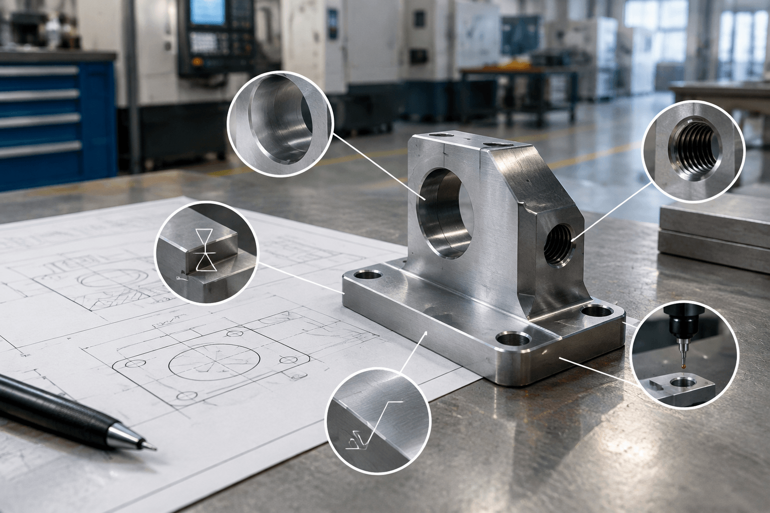
High precision metal parts are components made and accepted against defined drawing dimensions, geometric relationships, functional interfaces, and inspection criteria—not parts that merely carry a vague tight-tolerance label. A part is high precision when its critical features, such as hole location, thread form, profile, or mating surface, conform to the requirements that control its use and can be repeated in the intended production context.
For OEM engineering and sourcing teams, precision is therefore a controlled result rather than a universal number. The drawing revision, material, manufacturing route, finish, inspection method, and assembly conditions all determine whether a custom part is suitable for its application.
What Makes a Metal Part High Precision?
Precision means that the important characteristics of a part meet the requirements defined for its function. Those requirements may concern size, location, shape, surface condition, or how the part interacts with another component.
- Dimensional precision: A specified length, thickness, hole size, or thread feature stays within its drawing requirement.
- Geometric precision: Features maintain the required relationship to datums or to one another, such as hole location, profile, flatness, or alignment.
- Repeatability: Approved features are reproduced consistently across samples or production batches under the agreed process controls.
- Functional fit: Mating faces, fasteners, holes, and threads work together in the defined assembly, not only when checked separately.
Consider a hypothetical formed bracket with a hole pattern, threaded mounting points, and a coated contact surface. Its appearance may be excellent, but that alone does not prove precision. The hole pattern must relate correctly to the drawing datums, the threads must suit the mating fasteners, the formed geometry must align with the assembly, and the finish must not compromise the interface. A nominal dimension or attractive surface finish by itself is insufficient evidence.
Which Manufacturing Process Should Create Each Feature?
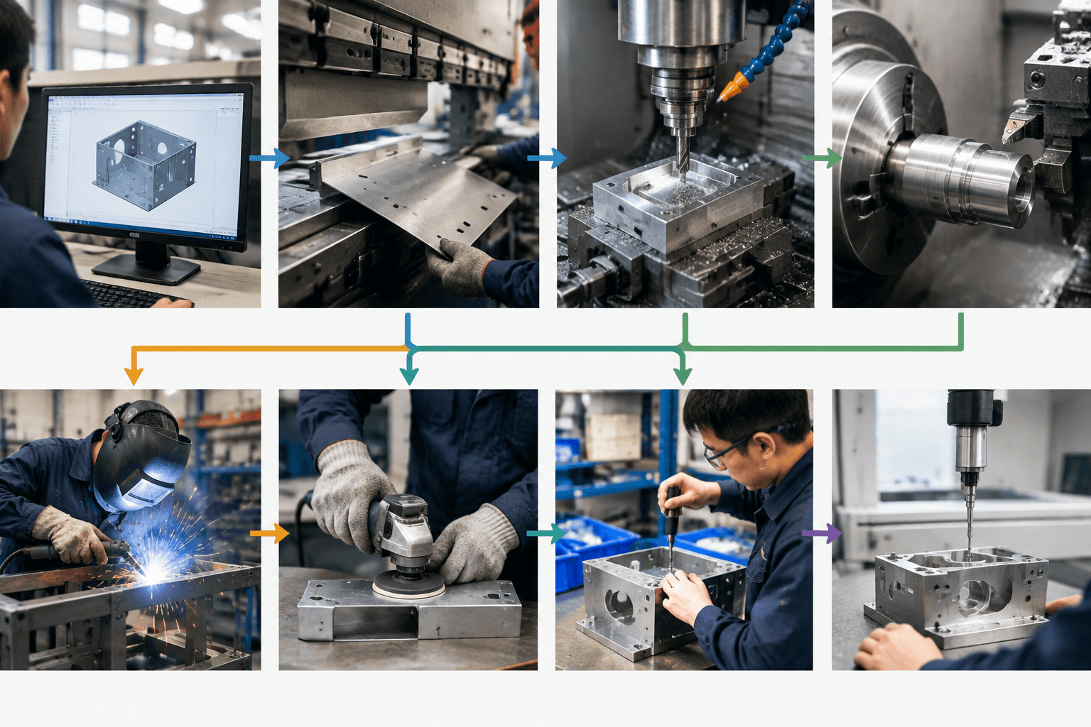
Process selection depends on geometry, material, quantity, critical features, and downstream fit. CNC machining is an umbrella term; CNC milling and CNC turning are different machining routes. A part may use one route, several routes, or no machining at all.
| Process | Primary role | Important limitation or interface |
|---|---|---|
| Sheet metal fabrication | Cutting, punching, bending, and forming sheet into brackets, enclosures, and panels. | Hole-to-bend relationships, formed geometry, edge condition, and material response require control; it is not the same as milling. |
| CNC milling | Removing material to create pockets, profiles, faces, and coordinated hole features on suitable workpieces. | Access, workholding, datum strategy, geometry, and quantity influence whether milling is appropriate. |
| CNC turning | Producing rotational features such as shafts, bores, diameters, and threads. | Turned parts may interface with sheet metal assemblies, but turning is a machining process rather than sheet metal fabrication. |
| Welding | Joining cut, formed, or machined components into a larger structure. | Heat, joint sequence, and fixturing can affect alignment and distortion, so the welded result still needs dimensional and visual checks. |
| Finishing | Providing a specified surface condition, appearance, protection, or coating. | Finish, masking, texture, or coating build-up may affect fit; a visual finish does not verify dimensions. |
| Assembly | Positioning and fastening parts so their interfaces operate together. | Assembly can reveal alignment or tolerance-stack issues, but it cannot replace inspection of the individual parts. |
| Inspection | Comparing features and results with the drawing, specification, and acceptance criteria. | Inspection verifies the manufacturing result; it does not create the feature or correct an unclear requirement. |
When machined features dominate the design, Custom CNC Machining From First Sample to Repeat Production can help explain how machining fits into sample approval and ongoing production planning.
How Should Design Intent Be Written Into the Technical Package?
Before a supplier can make and inspect a high precision metal part, the technical package must show what matters and how it will be accepted. A useful package normally includes:
- Drawing control: Provide the 2D drawing and, where relevant, the 3D CAD file with a clear revision. The supplier must know which document governs if files differ.
- Datums and tolerances: Identify reference datums, dimensional tolerances, geometric requirements, and critical characteristics. Do not rely on an unexplained note such as tight fit.
- Feature details: Define hole size, location, pattern, depth, and relation to edges; thread requirements; profiles; and edge or burr expectations.
- Material and finish: State the required material or grade, thickness where applicable, finish or coating, masking areas, and surfaces where finish could affect fit.
- Quantity and context: State prototype, first-sample, batch, or repeat-production status, together with mating parts, assembly orientation, fasteners, access, and required inspection records.
Ambiguous language creates interpretation risk. For example, a note saying all holes must align does not identify the reference features, while a note saying finish all surfaces may not identify masking or functional contact areas. The more directly a requirement connects a feature to its function and acceptance evidence, the easier it is to quote, produce, inspect, and repeat.
From Critical Feature to Acceptance Evidence: A High Precision Metal Part Specification Matrix
| Critical feature | Define in the package | Process note | Acceptance evidence |
|---|---|---|---|
| Hole | Size, location, axis, pattern, depth, and datum relationship. | Use the suitable cutting, forming, milling, or turning route. | Dimensional and location results tied to the current revision. |
| Thread | Thread requirement, depth, start, insert condition, and mating fastener. | Select a machining, forming, or insert approach as applicable. | Thread and location check against the drawing. |
| Mating interface | Contact surfaces, alignment, fit, masking, and functional finish. | Consider forming, machining, finishing, and assembly sequence together. | Dimension, geometry, finish, and agreed fit checks. |
| Formed or welded geometry | Bend locations, angles, joint position, appearance, and overall alignment. | Define sequence and fixturing considerations before production. | Post-process dimensional and visual inspection. |
| Material and finish | Material, thickness, surface requirement, coating, and masked areas. | Protect critical interfaces during finishing where specified. | Material and finish records or checks agreed in the package. |
| Assembly fit | Mating components, orientation, fasteners, clearances, and access. | Review tolerance stack and assembly order. | Fit or alignment check using the defined mating context. |
For a drawing-led example of a component where geometry and interfaces matter, see custom metal brackets built to your drawings.
How Are High Precision Metal Parts Inspected and Accepted?
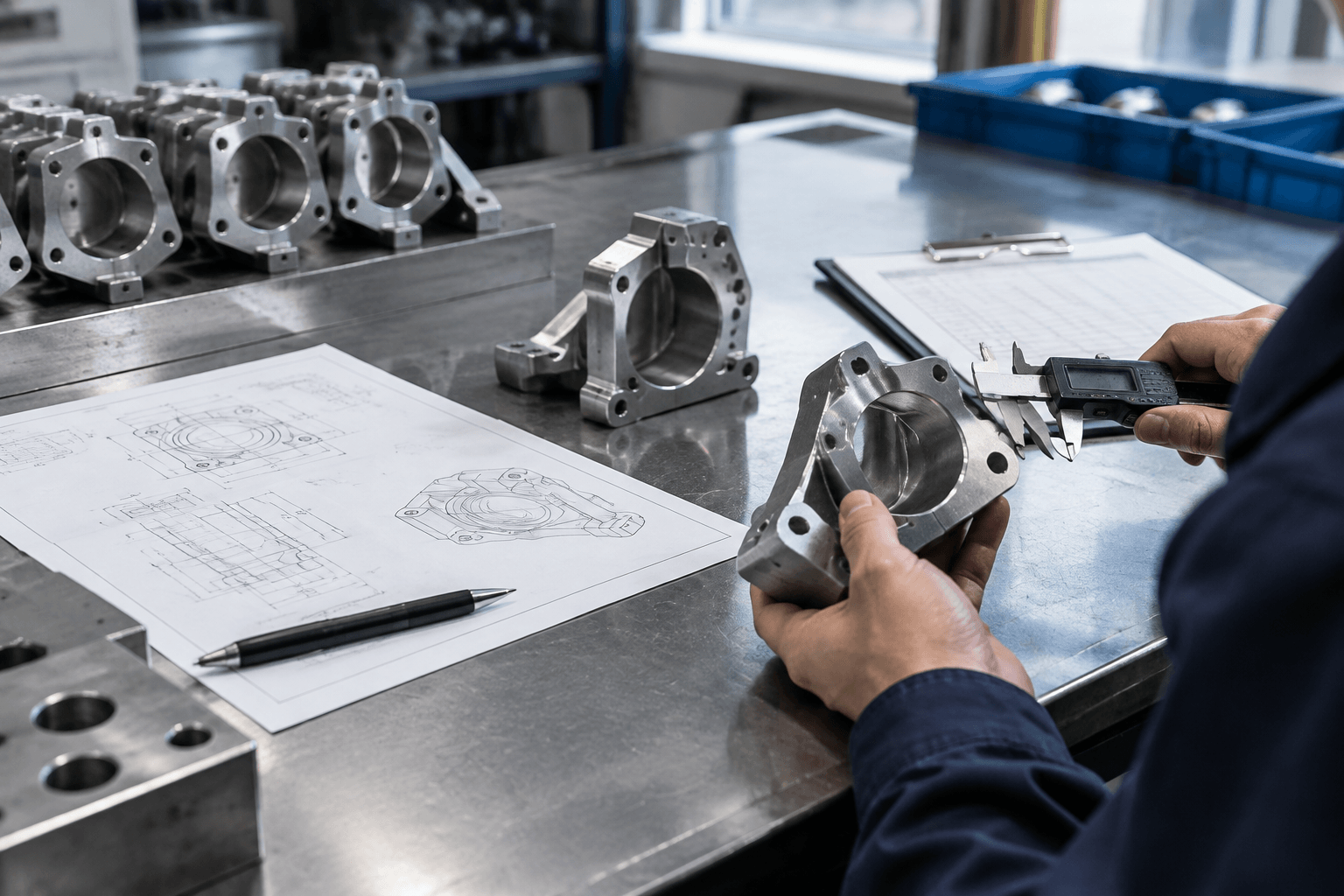
Inspection should mirror the acceptance criteria rather than rely on a generic statement that parts are inspected. A practical sequence separates several types of evidence:
- In-process control: Confirm setup, sequence, workholding, forming, welding, or machining conditions before the part is complete. This supports control but is not final proof.
- Final dimensional inspection: Compare dimensions and geometric relationships with the correct drawing revision and datum structure.
- Feature checks: Examine critical holes, threads, profiles, mating faces, edges, and burr conditions according to their specific requirements.
- Finish and visual review: Check the specified surface condition, coating coverage, masking, appearance, and visible defects without treating appearance as dimensional evidence.
- Assembly-fit check: Where fit is critical, use the defined mating part, assembly, or representative fixture and record the result separately from part-level measurements.
An inspection record should identify the drawing revision, sample or lot, critical feature references, results or status, and any nonconformance disposition. This evidence allows a buyer to connect a result to the requirement actually being purchased.
How Do Prototype Parts Stay Consistent in Repeat Production?
Repeatability begins when the first sample is treated as a process review, not only as a one-time part. The supplier and buyer should confirm the revision, material, process sequence, workholding or fixtures, critical features, finish sequence, and inspection approach before the approved method moves into repeat production.
In a hypothetical bracket project, a first sample might meet its individual dimensions but fail to install because the mating enclosure, fastener access, hole pattern, or finished contact surface was not defined. Reviewing the part with its assembly context can expose that risk earlier. Part-level compliance does not automatically guarantee final assembly fit unless the mating interfaces and assembly conditions are specified.
Revision control, first-sample feedback, retained inspection evidence, and checks on critical features during a batch help maintain consistency. Quantity and geometry also influence the balance between setup effort, process stability, inspection scope, cost, and schedule. A reliable estimate requires the complete part package rather than a keyword such as precision.
Frequently Asked Questions
What are high precision metal parts?
They are metal components manufactured and accepted against defined dimensional, geometric, functional, material, finish, and inspection requirements. Precision is application-dependent: a part is not automatically high precision because it is machined, polished, or described with a tight-tolerance phrase.
Are CNC-machined parts always high precision metal parts?
No. CNC machining includes many different applications and levels of requirement. Milling and turning can create controlled features, but whether the finished part is high precision depends on the drawing, datums, critical interfaces, repeatability expectations, and acceptance evidence.
How should tolerances, datums, finishes, and inspection requirements be specified?
Connect each requirement to a feature and its function. Identify the drawing revision, datums, tolerances, hole and thread details, material, finish and masking, mating context, critical characteristics, and the inspection record required for acceptance. Avoid undefined notes such as tight fit or inspect everything.
How is consistency maintained from a prototype to repeat production and assembly?
Use revision control, an agreed process sequence, suitable workholding or fixtures, first-sample review, documented feedback, and checks on critical features during production. Also define the mating parts and assembly conditions, because a compliant standalone part may still fail an undefined assembly interface.
Conclusion: Precision Is a Controlled Result
High precision metal parts are defined by controlled requirements and credible evidence. When holes, threads, geometry, material, finish, datums, mating interfaces, and inspection scope are clear, the manufacturing route and repeat-production controls can be evaluated on their actual fit for purpose.
For a technical project review, B2B OEM and ODM buyers can share a 2D drawing and/or 3D CAD file with revision information, material and finish requirements, quantity or production stage, critical dimensions and interfaces, assembly context, inspection or documentation needs, and a target schedule if relevant. Yishang serves B2B custom manufacturing projects, has more than 26 years of experience making custom sheet metal parts and metal products, exports to more than 50 countries, and holds ISO and RoHS certifications. Its team can review process fit, finish and assembly implications, and inspection alignment before formal pricing.