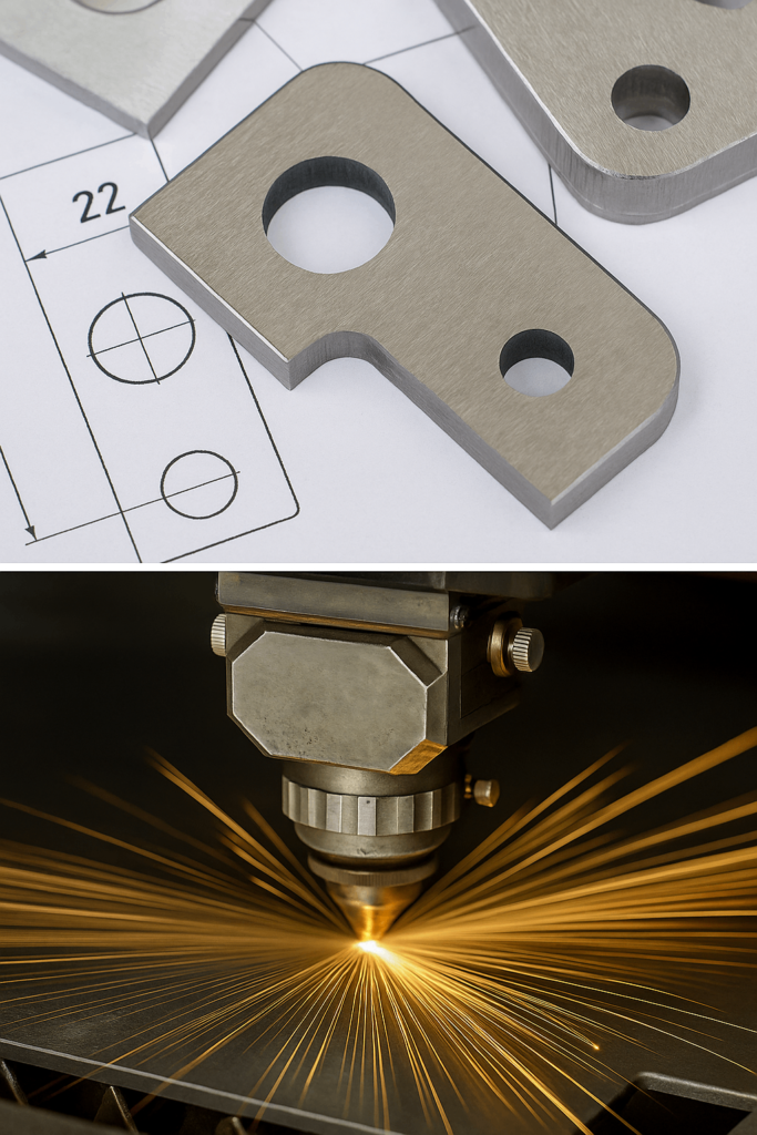
In cutting processes, kerf refers to the width of material removed by the cutting tool or cutting beam. It may seem small, but it can directly affect part dimensions, assembly fit, material usage, and batch consistency.
For buyers and engineers, kerf is not only a machine detail. It is a practical variable that influences whether parts fit correctly after cutting, bending, welding, or final assembly.
This guide explains what kerf means in fabrication, what changes cut width in real production, why kerf control matters for tolerance and material efficiency, and what buyers should confirm before placing an order.
Why Kerf Is a Design and Tolerance Variable
Kerf is not a fixed number. It changes with cutting method, material, thickness, machine condition, and process settings.
This matters because drawings and assemblies are based on finished dimensions, not only nominal toolpaths. If kerf is not considered correctly, even a small width difference can affect:
hole size;
slot fit;
tab-and-slot assembly;
panel alignment;
frame squareness;
weld gap consistency.
In multi-part assemblies, small kerf errors can accumulate and create visible or functional problems later.
Kerf size depends on both the cutting process and the actual production condition.
Common Influencing Factors
cutting method;
beam or tool size;
material type and thickness;
cutting speed;
gas, pressure, or cooling condition;
machine calibration and wear;
setup stability.
In laser cutting, focus condition, speed, power, and gas settings can all influence cut width. In CNC routing or milling, tool diameter and wear play a major role. In plasma or waterjet cutting, kerf may change with pressure, nozzle condition, or process setup.
Why CAM Defaults Are Not Always Enough
CAM software can apply kerf offsets, but default settings do not automatically reflect real cutting variation. Material changes, machine condition, and batch differences may still shift the actual cut width.
For this reason, buyers should not assume that software settings alone guarantee cutting accuracy.
Typical Kerf by Material and Method
Material
Cutting Method
Typical Kerf Width (mm)
Stainless Steel
Fiber Laser
0.10 – 0.15
Aluminum
CO2 or Laser Process
0.15 – 0.25
Mild Steel
Plasma
0.80 – 1.20
Acrylic
CO2 Laser
0.20 – 0.30
Wood / Plywood
CNC Router
1.50 – 3.00
These are only reference ranges. Actual kerf should still be confirmed according to machine condition, material, and thickness.
Kerf Offset and Cut Width Calculation
Kerf offset is the toolpath adjustment used to compensate for removed material. In practical terms, the toolpath may need to shift by half of the kerf width depending on whether the cut is internal or external.
This calculation is especially important for slots, tabs, mating parts, and other features where fit must be controlled closely.
Why Kerf Matters in Assembly, Cost, and Material Efficiency
When kerf is not controlled well, problems may appear in several ways:
slots become too tight or too loose;
tab-and-slot parts do not fit correctly;
welded assemblies develop uneven gaps;
panel alignment shifts;
scrap and rework increase.
For batch production, kerf errors are rarely isolated to one part. They often affect multiple parts and increase downstream correction work.
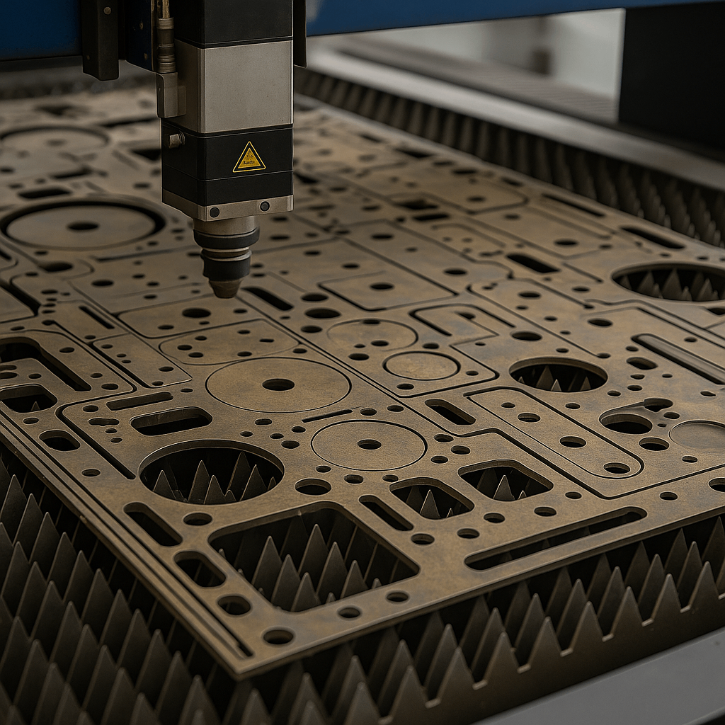
Kerf also affects sheet utilization. When cut width is planned correctly, nesting can be optimized more accurately, which may improve parts-per-sheet performance and reduce material waste.
How is cut width measured and adjusted for different materials and cutting methods?
Is kerf compensation reviewed only in software, or also verified on the machine?
How does the supplier manage tolerance risk when multiple mating parts are cut in the same project?
FAQ
What is kerf in fabrication?
Kerf is the width of material removed during cutting. It affects final part size and should be considered whenever dimensional accuracy matters.
Is cut width the same as kerf?
In many fabrication contexts, the two terms are used in a very similar way. Both refer to the width of material removed by the cutting process.
Why can small kerf differences cause large assembly problems?
Because kerf variation can accumulate across multiple slots, tabs, holes, or mating parts, especially in assemblies with repeated features.
Should buyers ask suppliers about kerf compensation?
Yes. It is especially important for projects involving tight tolerance, mating parts, visible alignment, or material-efficiency targets.
Custom Cutting Support from YISHANG
YISHANG Metal Products Co., Ltd. is a metal products factory with more than 26 years of experience in custom metal manufacturing for wholesale and OEM/ODM projects.
We support custom cutting and fabrication for parts such as enclosures, brackets, structural panels, display systems, vending machine parts, energy equipment components, and other OEM metal products.
Our manufacturing capabilities include:
sheet metal laser cutting;
bending;
deep drawing;
stamping;
welding;
CNC machining;
surface finishing;
design support;
prototyping;
assembly;
packaging;
quality inspection;
shipment support.
We are certified to ISO 9001 and RoHS. For projects where cut width, fit, and tolerance control are important, we can support drawing review, process evaluation, sample development, and repeat bulk production.
If you have any questions or need a quote, please send us a message. One of our specialists will get back to you within 24 hours and help you select the correct valve for your needs.