
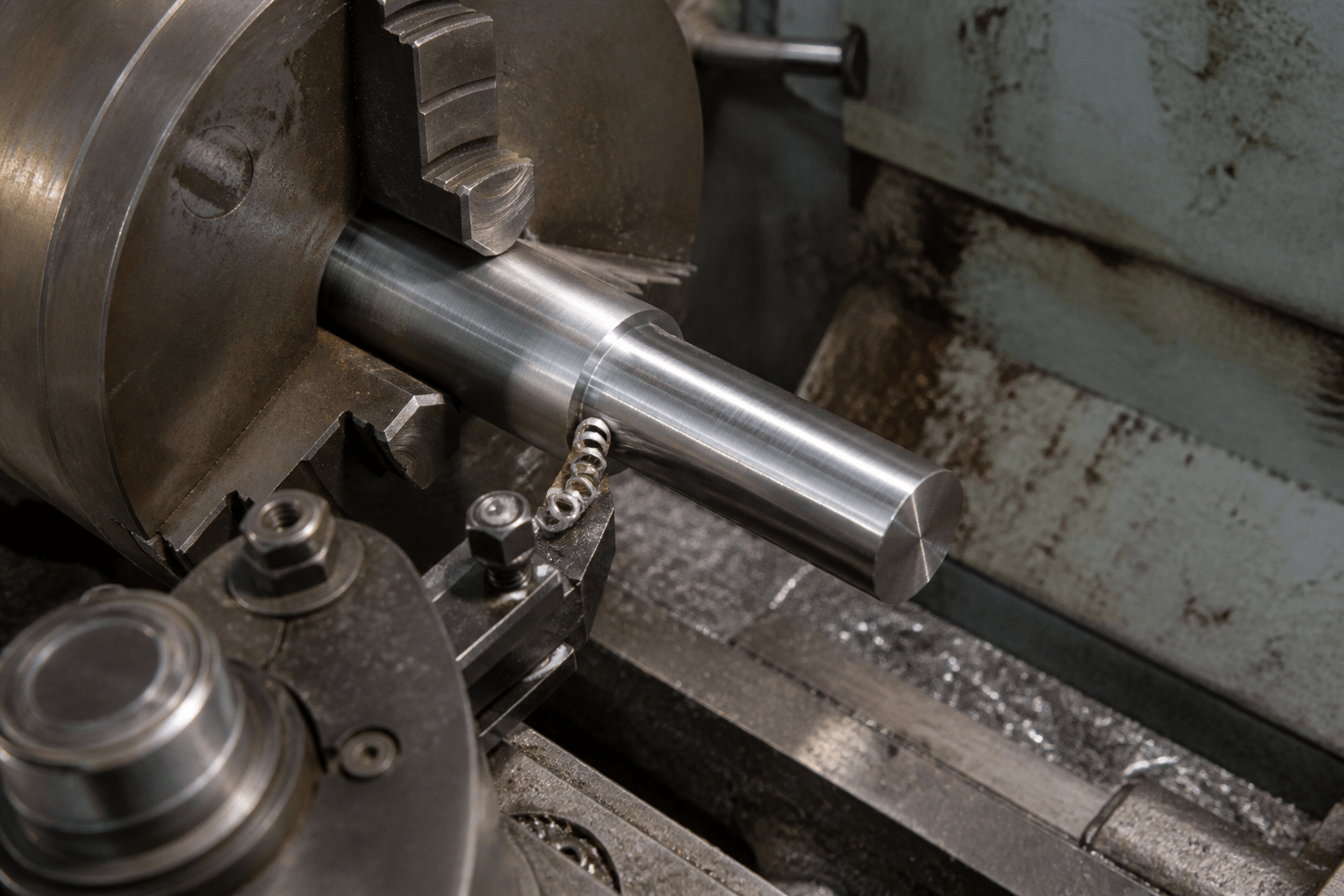
Lathe machining removes material while the workpiece rotates around a spindle axis and a cutting tool follows a controlled path. It primarily creates rotationally symmetric features such as outside diameters, faces, shoulders, tapers, grooves, bores, and threads. Milling primarily rotates the cutting tool. Sheet metal fabrication cuts and forms flat stock.
When reviewing a shaft, bushing, spacer, housing, or fabricated assembly, do not judge the process from a generally round appearance alone. Check whether the critical features relate to one axis. Also consider whether the setup can support the material and wall thickness without distortion. Secondary milling, finishing, or assembly operations may also affect the route. This article explains these process boundaries without repeating a catalog of lathe types.
The Defining Motion of Lathe Machining
A chuck, collet, set of centers, or purpose-built fixture grips and locates the stock or partly completed component. The spindle rotates the workpiece while the cutting tool feeds longitudinally, radially, or along a coordinated path. This relative motion shears material from the workpiece.
For an OEM drawing, this motion determines whether the machine can generate a feature directly from the spindle axis. A stepped shaft, a bushing with related inside and outside diameters, and a component with a tapered seat all suit this arrangement. The result also depends on cutting-edge geometry, material behavior, setup rigidity, chip evacuation, and access to the cutting zone.
Machine configuration affects usable capacity, automation, workholding options, and access to secondary features. For detailed configuration comparisons, see this guide to industrial machinery lathe types and usable capacity.
Operations and Their Resulting Features
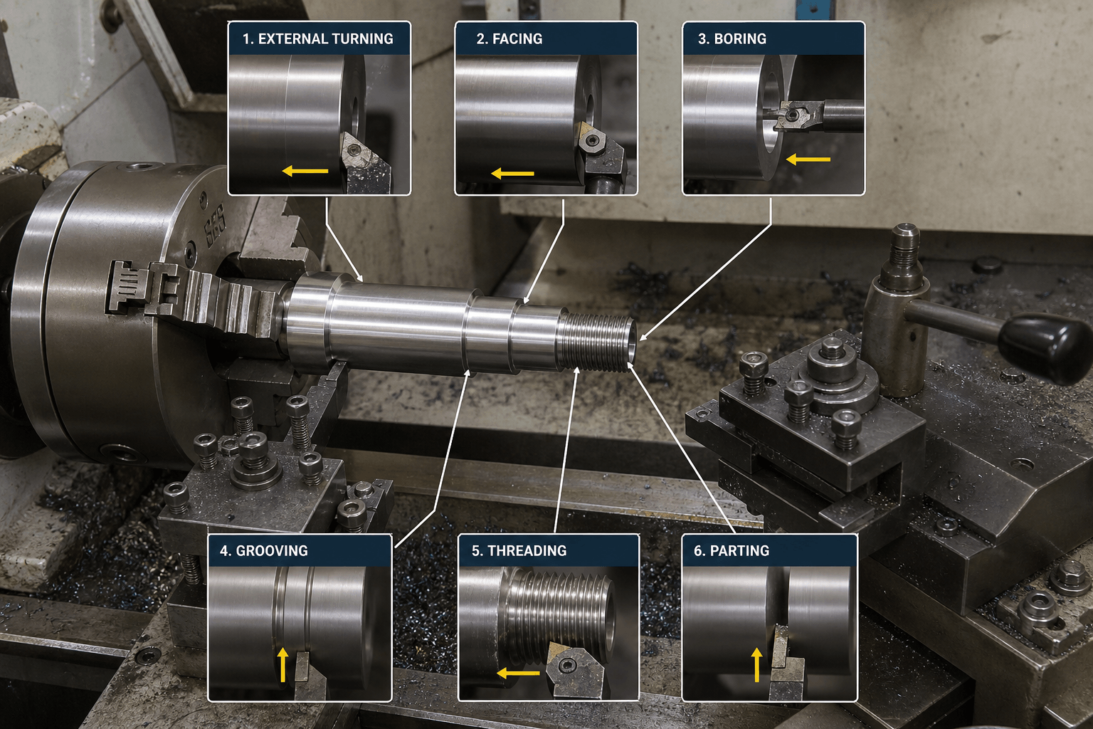
People often use turning as a general term for work performed on a lathe, but each operation creates a distinct feature. Identifying the operation helps define tooling, setup order, and inspection requirements.
| Operation | Tool action | Resulting feature |
|---|---|---|
| External turning | The tool feeds generally parallel to the spindle axis and removes material from the outside. | Straight diameters, steps, shoulders, and external profiles |
| Facing | The tool moves radially across the rotating end. | Flat end face, shoulder face, or controlled axial length |
| Boring | A boring tool enters an existing hole and cuts its internal surface. | Enlarged or corrected bore, internal step, or controlled axis relationship |
| Axial drilling | A drill advances along the spindle axis. | Centered hole for use as drilled or for later boring, reaming, or threading |
| Grooving | A narrow tool feeds into an external or internal surface. | Seal groove, retaining-ring groove, relief, or undercut |
| Parting | A narrow blade feeds toward the centerline and separates the component from the stock. | Separated component, sometimes followed by end-face finishing |
| Taper turning | The tool follows an angled or coordinated path. | Conical seat, tapered shaft, or transition surface |
| Threading | The machine synchronizes tool feed with workpiece rotation, or another tool produces the thread. | Internal or external thread with the specified form and pitch |
Drilling and boring are not interchangeable. Drilling initiates or extends a hole. Boring starts from an existing hole and can refine its diameter, straightness, surface, or relationship to turned features.
The basic turning motion does not create off-axis holes, flats, keyways, pockets, or slots. These features generally need milling or a separate drilling setup. Live tooling can combine selected operations when the equipment supports the required access and control. The actual drawing must still guide the feasibility review.
Geometry, Support, and Tool Access
A short, rigid component with accessible external diameters usually presents fewer challenges than a slender shaft, deep-bore component, or thin-walled sleeve. No universal length-to-diameter threshold determines feasibility. Material, cutting force, tool overhang, support, diameter, tolerances, and surface requirements all affect vibration risk. Depending on the component, a tailstock, steady rest, or between-centers arrangement can provide additional support.
Thin walls create a different problem. Clamping force can deform a delicate diameter during cutting. The surface may measure round while the workholding constrains it, then become lobed or out of round after release. The process plan must account for clamping force, contact area, locating surfaces, and the removal sequence. Soft jaws or sacrificial support may also help with suitable geometries.
Workholding affects rigidity, concentric relationships, deformation risk, and changeover:
- Chucks accommodate a broad range of stock and shapes. Jaw contact, gripping force, jaw condition, and repeat loading can affect runout and deformation.
- Collets distribute contact around compatible stock and can promote consistent repeat loading. Their gripping range and acceptable geometry remain more limited.
- Between-centers holding references center features at both ends. It can support the machining of several outside diameters about a common axis. Center quality and the driving method form part of the process plan.
- Purpose-built fixtures and soft jaws can locate irregular shapes or previously machined surfaces. Geometry, quantity, setup effort, and changeover frequency determine whether they make practical sense.
Interrupted cuts repeatedly load and unload the cutting edge as it crosses slots, openings, or uneven stock. Deep internal features increase tool overhang and make chip evacuation harder. Narrow grooves and adjacent shoulders restrict tool clearance. These conditions can change the tooling, operation sequence, workholding method, or secondary-process requirements.
Material Behavior During Turning
Material grade and condition affect chip formation, heat generation, work hardening, built-up edge, burrs, and deformation. A similar part in carbon steel, stainless steel, aluminum, brass, or engineering plastic may therefore need different tools and cutting conditions.
| Material group | Practical turning considerations |
|---|---|
| Carbon steel | Carbon content, alloying, hardness, and heat treatment change cutting force, chip formation, and tool wear. Free-machining, structural, and hardened grades do not behave alike. |
| Stainless steel | Many grades generate substantial heat. Some also work-harden when a tool rubs instead of cutting. Stable engagement, chip control, tool condition, and heat management need attention. |
| Aluminum | Cutting forces can be relatively low, but some alloys form built-up edge or long chips. Sharp tool geometry, chip evacuation, burr control, and surface protection may matter. |
| Brass | Many grades produce manageable chips, but composition and condition influence behavior. Tool geometry, burr formation, surface requirements, and material restrictions still need review. |
| Engineering plastics | Low stiffness, thermal expansion, heat sensitivity, and moisture response can change size and roundness. Clamping and cutting forces can also deform the component. |
Select tool grade, tool geometry, coolant strategy, feed, and cutting speed for the specific alloy, condition, diameter, and setup. Generic speed values lack meaning without tool-maker data and setup validation. Plating, anodizing, passivation, painting, and heat treatment are separate treatment operations. Grinding may follow turning when the drawing or material condition calls for it.
Drawing Relationships and Inspection
A turned-component drawing must communicate more than nominal diameters. Diameter tolerances define allowable size variation. Length tolerances control overall length, shoulder spacing, and groove location. Surface roughness describes texture, but it does not control size, form, runout, or relationships between separate features.
Circular runout evaluates variation at individual cross-sections while a surface rotates relative to a datum axis. Total runout evaluates variation across a broader surface during rotation. Coaxial requirements define the intended relationship between cylindrical feature axes. Datum selection establishes the reference for machining and verification.
Measuring each diameter separately can confirm size without proving the required axis or face relationship. Inspection methods may include micrometers, bore measurement, thread gauges, surface roughness measurement, rotational runout checks, and coordinate measurement. The drawing, datum simulation, feature access, required resolution, sampling plan, and reporting requirements determine the appropriate method. Yishang’s quality control page provides broader information about dimensional verification.
A thread designation should define the form, nominal size, pitch or threads per unit length, and class or tolerance. It should also state handedness when relevant. Usable thread length, entry chamfers, reliefs, coatings, and inspection expectations need definition when they affect fit or assembly.
Choosing the Manufacturing Route by Geometry
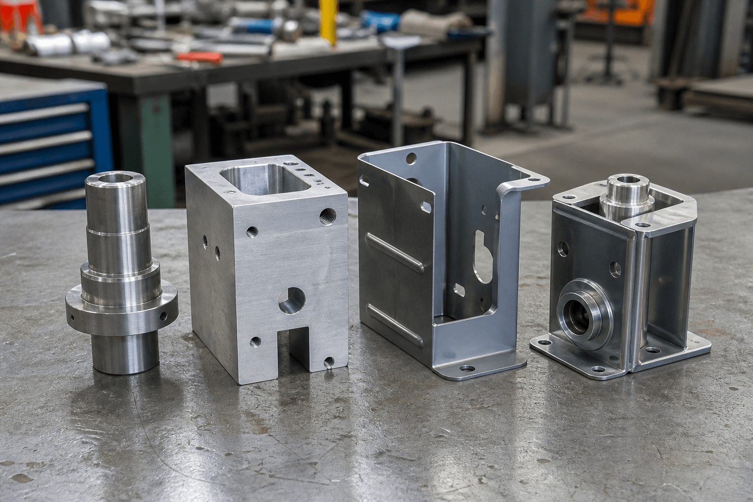
Route selection should follow the dominant geometry and the complete assembly. Turning suits rotational solids and axis-related features. Milling suits prismatic geometry and features approached from different directions. Sheet metal fabrication creates thin-walled structures through cutting, bending, welding, and assembly. A product can use all three routes, but each process creates different features.
| Dominant geometry or requirement | Likely route | Process implication |
|---|---|---|
| Rotational outside profiles, shoulders, tapers, or grooves | Lathe machining | The tool follows the spindle axis to create rotational surfaces. |
| Centered bore related to outside diameters | Drilling, boring, and turning | A controlled setup can maintain the specified relationships among rotational surfaces. |
| Off-axis holes, flats, slots, or pockets | Milling or combined machining | The features need another setup unless suitable equipment provides the necessary access and control. |
| Prismatic block with several planar faces | CNC milling | The geometry depends on cutting-tool access from multiple directions rather than workpiece rotation. |
| Thin-walled enclosure with bends and cutouts | Sheet metal fabrication | Cutting, bending, welding, and sheet assembly differ from lathe machining. See custom sheet metal structures and assemblies. |
| Welded frame or housing with critical interfaces | Fabrication with selective machining | Welding creates the structure. Machining can establish bearing seats, mounting references, or other functional interfaces. |
| Fabricated panel requiring a bushing, spacer, or shaft support | Combined route | Turning creates the rotational component before the specified joining or assembly step. |
A turned bushing may fit into a laser-cut and bent enclosure. A turned shaft may form part of a welded assembly. In both cases, turning creates the rotational component while fabrication and joining create the surrounding structure. Review the assembly drawing, joining method, finish compatibility, and inspection requirements together.
Where RFQ Assumptions Create Cost and Production Risk
Many sheet metal fabrication problems begin before production starts. If drawings, tolerances, finish expectations, material grades, or assembly requirements are unclear, suppliers may quote based on different assumptions. That can make prices difficult to compare and may lead to rework, cosmetic rejection, assembly misalignment, or production delays later.
For OEM buyers, the goal is not simply to request the lowest price. The goal is to make sure each supplier is quoting the same manufacturing reality. Before confirming an order, clarify which dimensions are fit-critical, which surfaces are cosmetic, whether prototypes must match batch-production conditions, and how finished parts will be inspected.
Frequently Asked Questions
What lathes machining details should buyers define before requesting a quote?
Buyers should define the functional requirement, drawing notes, critical dimensions, material or process expectations, and any inspection points related to lathes machining. This helps suppliers quote the same manufacturing scope instead of making different assumptions.
How can RFQ details affect cost, fit, or lead time?
RFQ details can change tooling, forming, welding, finishing, inspection, or rework requirements. If buyers do not clarify it early, two supplier quotes may look comparable while covering different production risks.
Why should drawing requirements be reviewed before prototype approval?
drawing requirements may look acceptable on a single sample but become harder to control during batch production. Buyers should confirm whether the prototype reflects the same process, finish, and inspection conditions expected for production.
What inspection points matter most for lathes machining projects?
Important inspection points usually include fit-critical dimensions, holes or mating areas, cosmetic surfaces, finish build-up, welded or formed features, and any dimensions that affect downstream assembly. These points should appear in the RFQ or drawing notes.
How can buyers reduce prototype approval risk before batch production?
Buyers can reduce risk by clarifying drawings, locking key material and finish assumptions, defining inspection timing, approving a representative sample, and confirming which dimensions or surfaces require tighter process control.
How can Yishang help review lathes machining requirements?
Yishang can review drawings, RFQ notes, material requirements, tolerance expectations, finish details, samples, and assembly needs to identify unclear assumptions before quoting or batch production.