
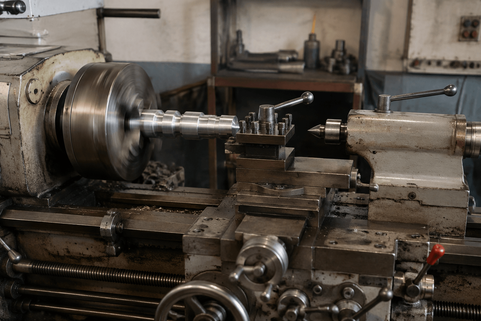
“Lathing machine” usually means a metal lathe or turning machine: it rotates a workpiece on a spindle while a cutting tool feeds along or toward it to remove material. For an OEM buyer reviewing a shaft, bushing, or threaded round component, the key process question is whether the part’s main features follow one axis of rotation; if they do not, milling or fabrication may be a better route.
Short answer: A lathe produces cylindrical, conical, bored, threaded, grooved, and parted features by controlling the movement between rotating stock and the cutting tool. It is most suitable for solid parts whose main features share an axis of rotation, rather than for flat or formed sheet-metal components.
Industrial terminology: lathe, lathing, and turning
When an OEM drawing or supplier listing uses “lathing machine,” confirm the terminology before comparing equipment or quotes. The usual industrial terms are a lathe machine for the machine tool, and lathing or turning for the material-removal operation. “CNC lathe” and “CNC turning machine” usually describe related equipment, while a turning center may add driven tools or other machining functions.
A metal lathe is designed around solid bar, tube, or other stock held on a spindle axis. It should not be confused with woodworking equipment, and turning is not the same process as laser cutting, punching, bending, welding, or other sheet-metal work. A turned pin can be installed in a fabricated enclosure, but the two components still have different manufacturing routes.
CNC machining is the broader category, and turning is one operation within it. This article focuses on metalworking lathes and the process-selection questions an OEM buyer should resolve before comparing suppliers.
How the machine turns raw stock into features
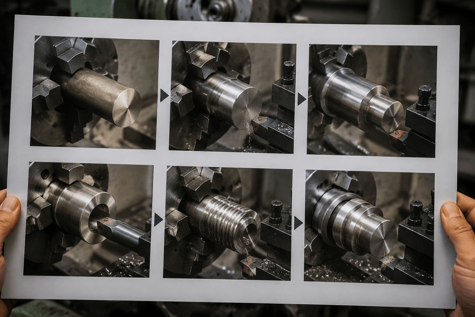
For a buyer, the sequence below connects the drawing to the setup, cutting operations, and inspection plan. The exact route depends on the drawing, material, quantity, and machine configuration:
- Review the drawing and select stock. Confirm the revision, material grade and condition, finished dimensions, datums, threads, geometric tolerances, surface requirements, and allowance for machining. The blank may be bar, tube, or cut stock.
- Establish workholding. A chuck or collet attached to the spindle locates the workpiece. A tailstock center or another support may be needed for long or slender parts. Clamping must provide stability without distorting the part.
- Set the tools and coordinates. The carriage, cross-slide, toolpost, or CNC turret positions external and internal tools. Tool offsets, tool orientation, and the work coordinate system are checked before cutting.
- Rotate the workpiece. The spindle turns the stock under controlled cutting conditions. On a manual lathe, the operator controls the movements directly; on a CNC machine, programmed axis motion coordinates spindle and tool movement.
- Generate the outside form. Facing moves a tool across the end to create a flat surface. Longitudinal feed produces an outside diameter, while transverse or radial movement can create shoulders, grooves, and parting cuts. Compound-slide or coordinated CNC movement can produce a taper.
- Machine internal and detail features. With suitable tooling and setup, the lathe can drill an axial hole, enlarge it through internal boring, cut grooves, produce threads, and part the finished component from the stock.
- Measure critical features. Dimensions such as diameters, lengths, bores, threads, runout, and surface condition are checked during or after machining using a method suited to the drawing requirements.
- Remove and handle the part. After the final operation and inspection, the part is parted off or removed from the workholding, then deburred and protected according to the drawing or purchase requirements.
The recurring rule is that tool movement is planned in relation to the rotating axis. That is why turning is efficient for round components and less natural for features that do not follow a common axis.
Turning, milling, or sheet metal? Match the geometry to the process
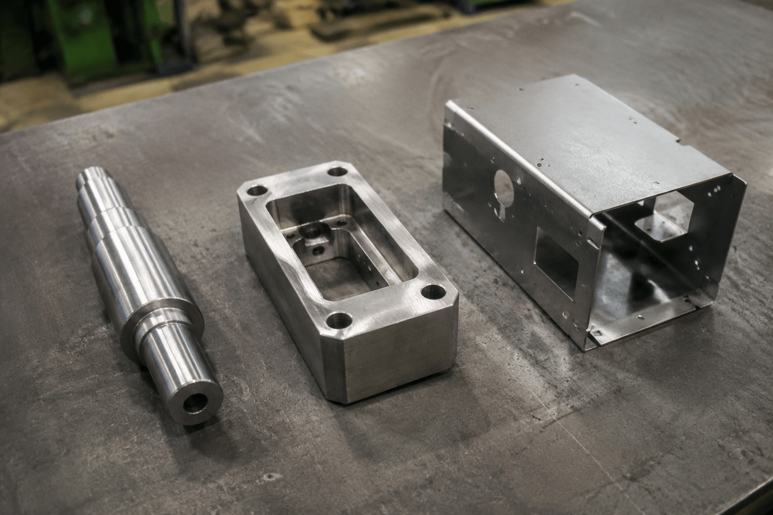
If a part begins as round stock but also needs pockets, flats, or a fabricated enclosure, decide the process feature by feature before requesting prices. Standard turning is strongest when the primary features are rotationally symmetric; the comparison below separates common routes.
| Part or feature pattern | Likely process | Process note |
|---|---|---|
| Shafts, pins, bushings, collars, spacers, and threaded round parts | Lathe or CNC turning | Good fit when outside diameters, bores, shoulders, tapers, and threads are arranged around one main axis. |
| Pockets, slots, flats, cross-holes, and non-rotational profiles | Milling or a machining center | A fixed workpiece and rotating cutter are generally better suited to features that do not result from axial rotation. |
| Round body with off-axis holes, flats, or milled slots | Turning center or turn-mill equipment | May reduce setups, but the supplier must confirm the actual live-tooling, spindle, and workholding configuration. |
| Flat profiles, bend lines, brackets, panels, and enclosures | Laser cutting, punching, and bending | These are sheet-metal routes, not lathe operations. See custom sheet metal fabrication when the design is flat or formed. |
| Example: turned insert used with a fabricated enclosure | Separate or hybrid process route | The insert may be turned while the enclosure is cut and formed. They may need different suppliers, drawings, and inspection plans. |
A square part or plate should not be assigned to a basic lathe simply because a supplier advertises CNC equipment. If a design combines a turned body with pockets or off-axis features, compare a turn-mill setup with a separate turning-and-milling sequence. The broader CNC machining route may be relevant when several machined feature types must be coordinated.
Early process-fit check: Before requesting unit pricing, provide the drawing, material, quantity, and critical features and ask the supplier to identify the proposed setup, workholding, and inspection method. A qualified supplier should explain how each feature will be made rather than treating every CNC process as interchangeable.
Choosing among manual lathes, CNC turning, and turning centers
Machine choice is a setup decision as much as a volume decision. Geometry, repeatability, programming effort, tooling, and inspection requirements should be weighed together rather than treating manual or CNC equipment as universally better.
Manual or engine lathe
A manual lathe generally suits one-off work, repairs, maintenance, operator-led setups, and some simple prototypes. It can be practical when programming would add more effort than the job justifies, but repeatability depends strongly on operator technique, setup discipline, and measurement.
CNC turning machine
A CNC lathe uses programmed toolpaths, offsets, and repeatable sequences. It is often better suited to repeat production because tool changes, machining steps, and inspection points can be organized around the same drawing. Programming, workholding, tooling, and proving the first part still require engineering work.
Turning center or mill-turn equipment
A turning center may combine spindle turning with a turret, driven tools, a second spindle, or other features. This can reduce handling for parts with rotational surfaces plus cross-holes, flats, or slots. The name alone does not confirm a particular capability, so the supplier should identify the actual machine configuration and proposed sequence.
Production volume is important, but a CNC label does not by itself prove capability. Ask the supplier to connect the machine configuration and inspection plan to the required tolerance, thread, and surface specification.
Material and stability controls that shape the finished part
Material affects more than the cutting tool. It changes cutting conditions, chip behavior, cooling or lubrication, workholding needs, and dimensional stability, so the supplier should validate the route against the alloy, condition, geometry, and drawing rather than apply generic speed-and-feed values.
| Material family | General turning considerations |
|---|---|
| Steel | Grade and hardness influence insert geometry, chip breaking, cutting forces, heat generation, coolant selection, and tool wear. |
| Stainless steel | Some grades work-harden and retain heat. Stable engagement, suitable tooling, chip evacuation, and avoiding tool rubbing are important. |
| Aluminum | Sharp tooling and effective chip evacuation can help limit built-up edge, burrs, and surface damage. Lubrication depends on the alloy and finish requirement. |
| Brass | Machinability varies by alloy. Tool edge condition, chip behavior, burr control, and the required appearance still need to be verified. |
| Engineering plastics | Heat, elastic deflection, clamping marks, and temperature-related size change can be significant. Sharp tools, support, and controlled clamping are often important. |
Workholding is a common source of variation. Chucks, collets, soft jaws, or centers should match the diameter, wall thickness, and locating surfaces. Excessive overhang can cause vibration or deflection, while excessive clamping force can distort thin-wall parts. The supplier should explain how the part will be supported and how the datum will be maintained between setups.
Tool wear, thermal change, workholding error, and spindle or tool alignment can influence diameter, length, concentricity, runout, threads, and surface roughness. These requirements are related but are not interchangeable drawing callouts. Critical features should therefore be defined with their datums and inspected using a method appropriate to the drawing. A documented quality-control plan is useful when first-article approval, sampling, or dimensional reports are required.
Turning-part brief: details that prevent an apples-to-oranges quote
An OEM inquiry should describe the actual part and production stage, not simply state that a lathing machine is required. Complete inputs help suppliers quote the same scope and expose differences in setup or inspection assumptions:
- Drawing package: Provide the current 2D drawing, revision level, units, datums, and a 3D CAD file where it helps explain the form.
- Material: State the grade, condition, blank or stock assumption, and required material documentation.
- Demand: Give the prototype or production stage, initial quantity, batch size, and expected repeat or annual demand.
- Critical features: Identify important diameters, lengths, bores, threads, datums, runout or concentricity requirements, and geometric tolerances.
- Finish and handling: Specify surface roughness, deburring, cleanliness, marking, packaging, and any post-machining treatment or separate assembly requirement.
- Inspection: Define first-article expectations, sampling, reports, measurement records, and the procedure for nonconforming or deviating parts.
- Related components: State whether the project also includes sheet-metal enclosures, frames, brackets, panels, or welded assemblies so the manufacturing boundary is clear.
When comparing supplier responses, check the proposed process route, actual machine type, workholding method, tooling or fixture assumptions, material yield, inspection equipment, first-article approach, batch controls, packaging, and deviation handling. Setup, programming, one-time tooling or fixture costs, inspection, material utilization, and batch size can all affect quoted cost and schedule. Compare assumptions and exclusions, not only unit prices.
Before placing an order, ask the supplier to confirm that the requested turning work is within its verified production scope and that its proposed equipment matches the part features. For mixed projects, send the turning drawing separately from sheet-metal drawings so each process route and inspection responsibility is clear.
Frequently Asked Questions
These questions resolve terminology that can otherwise send a drawing to the wrong process route.
Is a lathing machine the same thing as a lathe machine?
Usually, yes. “Lathing machine” is common search wording for a metal lathe. In industrial terminology, the machine is a lathe or turning machine, while lathing or turning describes the operation performed as the workpiece rotates.
What is the difference between a lathe and a turning machine?
The terms often overlap. A lathe is the machine tool and turning is the operation. “Turning machine” may describe a conventional or CNC production lathe, while “turning center” can imply additional tooling or machining functions. Confirm the supplier’s actual configuration.
Can a lathe make square parts, flat plates, or sheet-metal enclosures?
A basic lathe is intended mainly for rotationally symmetric work. Special setups or live tooling may create limited non-round features, but milling is generally more suitable for plates and pockets. Laser cutting and bending are separate routes for sheet-metal enclosures.
Is a manual lathe or CNC lathe better for prototype and production parts?
Neither is universally better. A manual lathe can suit one-off repairs or simple prototypes, while CNC turning is generally better suited to repeat production and controlled sequences. Off-axis features may require a turning center or a separate milling operation.
Need to clarify the route before requesting an RFQ? Send a current 2D drawing or 3D CAD file, material, quantity, production stage, critical diameters, threads, tolerances, and surface requirements. If the project also includes custom sheet-metal parts, enclosures, frames, or welded assemblies, include those drawings as well. Yishang can review whether that sheet-metal portion fits its verified custom fabrication scope; this does not represent unverified lathe-turning capability.