
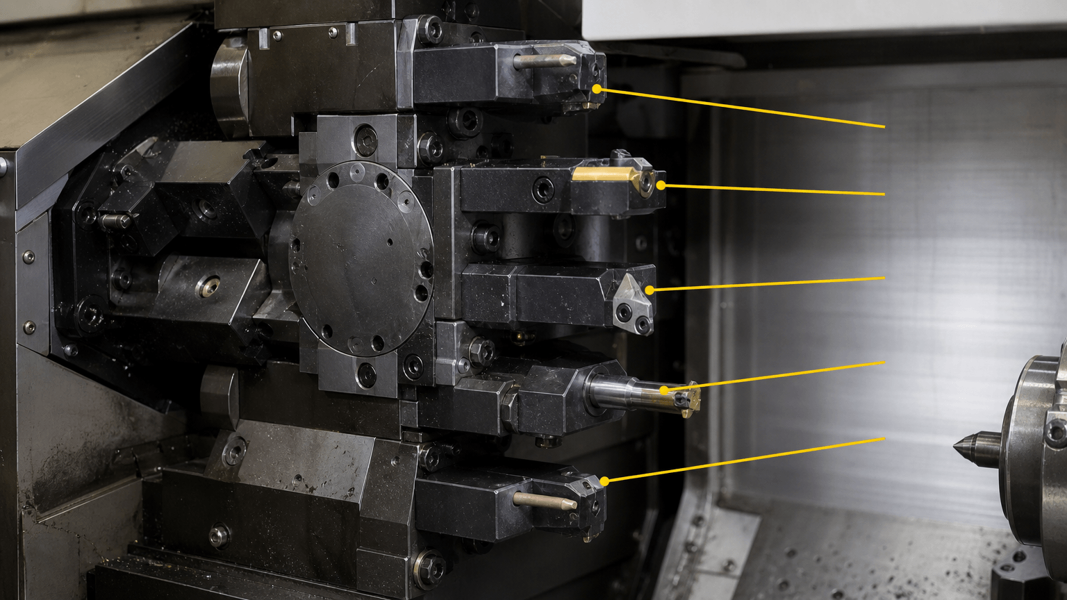
Quick answer: Machinist lathe tools are cutting and forming tools used on manual or CNC lathes. The workpiece normally rotates while the tool is positioned and fed into it; a boring bar generally does not rotate like a milling cutter.
Choose the tool by operation first. Then check the workpiece material, hardness, cutting continuity, access, geometry, machine rigidity, quality target, and production objective.
Chucks, collets, centers, coolant systems, toolposts, turrets, and measuring instruments support the operation. They are not cutting tools.
Define the category, then match the operation
A drawing may combine turned diameters, a threaded boss, a precision bore, and a fabricated enclosure. The tooling review should separate the rotational features that require lathe work from sheet metal, welding, finishing, assembly, and inspection requirements.
Single-point tools remove material with a defined cutting edge. Drills and reamers are related hole-making tools. Knurling wheels form a pattern by displacing material rather than cutting it in the same way as a turning insert.
| Operation | Primary feature | Typical tool form | Access limitation | Chip concern | Common mistake |
|---|---|---|---|---|---|
| External turning and facing | Outside diameters, shoulders, faces | Single-point or indexable insert | Shoulder and holder clearance | Clear chips; avoid recutting | Wrong hand, nose radius, or chipbreaker |
| Profiling | Convex, concave, blended contours | Profile insert, form tool, or round nose | Contour depth and contact length | Long contact can pack chips | Using a general roughing tool in a restricted profile |
| Boring | Internal diameters and shoulders | Boring bar with cutting insert | Existing hole, bore ratio, overhang | Internal chips need an evacuation path | Allowing excess overhang or treating the bar as rotating |
| Grooving | External or internal grooves | Grooving insert or narrow blade | Slot width, bottom, and side clearance | Narrow slots trap chips and heat | Choosing an insert too wide or deep |
| Parting | Separating the finished part | Parting blade or cutoff insert | Alignment, rigidity, full-diameter engagement | Deep cuts need controlled chip evacuation | Excessive stick-out or poor center alignment |
| Threading | Internal or external threads | Threading insert or form tool | Profile, flank access, relief, runout | Synchronized feed and chip formation | Wrong profile, hand, or orientation |
| Drilling | Creating holes | Twist or indexable drill | Tailstock or turret alignment and depth | Deep holes restrict coolant and chips | Expecting the drill to correct misalignment |
| Reaming | Finishing an existing hole | Reamer | Pre-hole, allowance, alignment, access | Small allowance limits chip space | Using a reamer to correct a poor pre-hole |
| Knurling | Raised grip or appearance pattern | Forming wheels or knurling head | Support, pressure, alignment, tracking | Displaced material creates forming load | Treating it as ordinary single-point cutting |
Drills and reamers may be held in a tailstock or turret while the workpiece rotates. Live tooling on a suitably equipped CNC machine can rotate a tool. That is a different configuration from the ordinary lathe arrangement.
Illustrative project examples
These hypothetical project patterns show why the feature and setup matter more than the broad label lathe tool.
- Turned shaft: An outside diameter and shoulder start with an external turning or facing tool. A relief groove or cutoff feature needs separate access and chip control.
- Flanged sleeve: An existing bore calls for a boring bar. Check bore depth, bar overhang, and internal chip evacuation. A drill creates the hole but does not replace the boring operation.
- Threaded boss: External threading needs a matching profile, approach, hand, relief, and runout. A general turning insert is not automatically a threading tool.
- Fabricated enclosure: Flat panels and welded frames should be reviewed as sheet-metal or fabrication work, even when the assembly also includes turned standoffs.
Choose material, coating, and geometry as one system
Once the operation is known, compare toughness, hot hardness, wear resistance, edge strength, shock sensitivity, and the practicality of sharpening or replacing the edge.
| Tool material | Toughness and shock | Heat and wear behavior | Edge or maintenance logic | Starting application logic |
|---|---|---|---|---|
| High-speed steel | Tough and comparatively forgiving | Lower hot hardness than carbide | Can be ground or reground | Manual work, custom forms, lower-intensity cuts |
| Uncoated carbide | Less shock-tolerant; grade controls toughness | Good hot hardness and wear resistance | Commonly a replaceable insert | Productivity where the setup is reasonably stable |
| Coated carbide | Substrate and edge preparation set toughness | Coating may improve heat, abrasion, or chemical-wear resistance | Match coating and grade to the cut | Production shortlist after toolmaker data review |
| Ceramic | Sensitive to shock and vibration | Very high hot hardness in suitable cuts | Specialized replaceable edge | Stable, often continuous, wear-focused work |
| Cermet | Less forgiving in heavy interruption | Wear-oriented in suitable steel finishing | Sharp replaceable edge | Stable finishing rather than unstable heavy cuts |
| CBN | Grade and edge preparation control shock tolerance | Strong performance on selected hardened ferrous work | Specialized replaceable edge | Hardened steel or selected cast iron with rigidity |
| PCD | Hard but impact-sensitive | High abrasion resistance in suitable nonferrous and composite work | Specialized edge; confirm application limits | Abrasive aluminum, nonferrous alloys, or composites |
Common ISO workpiece-group shorthand can organize an initial search. P commonly refers to steels, M to stainless steels, K to cast iron, N to nonferrous metals, and H to hardened materials. This shorthand does not replace the selected toolmaker’s grade and cutting-data chart.
- Aluminum and other nonferrous metals: Often favor a sharp, positive, well-finished edge. Review carbide or PCD after checking alloy, abrasiveness, cutting continuity, and finish.
- Carbon and alloy steels: Often start with carbide or coated carbide. Confirm the grade against hardness, interruption, coolant, and the roughing or finishing task.
- Stainless steel: Needs a sharp but adequately tough edge. Heat and chip control are important because the cutting condition can become unstable quickly.
- Cast iron: Abrasive grades may lead to a carbide, ceramic, or CBN review. Rigidity and the presence of hard spots still matter.
- Hardened ferrous materials: May justify CBN or another heat-resistant solution. The decision depends on hardness, continuity, rigidity, and the required finish.
- Composite applications: Abrasion and reinforcement can justify a PCD review. Confirm the material system and edge limitations before selection.
Continuous cuts can support a wear-focused tool with lower shock tolerance. Interrupted cuts, hard spots, poor rigidity, or vibration increase the value of edge strength and toughness.
Include heat treatment, hardness, coolant delivery, tool overhang, and workholding with the material name. Material alone is not enough.
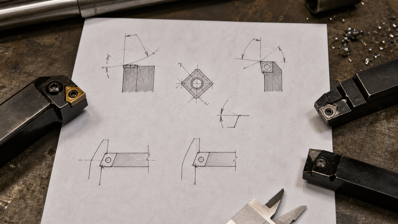
Geometry checks
                           chip flow ↑
                    rake face / chipbreaker
                                      /
feed direction → principal cutting edge ─┐
                                          └─ nose radius
workpiece surface ────────────────────────┘
                         clearance face / clearance angle

lead or approach angle: edge orientation relative to feed
insert shape and handedness: plan-view decisions
- Rake: More positive rake can reduce force and help ductile materials. It can also weaken the edge. A stronger edge tolerates interruption but may increase force and heat.
- Clearance: Too little clearance causes rubbing, heat, and poor finish. Too much clearance weakens edge support.
- Lead or approach angle: This changes chip thickness, contact length, access, and radial-versus-axial force distribution.
- Insert shape and edge preparation: Robust shapes and supported edges suit heavy or interrupted work. Smaller shapes can improve access but reduce impact resistance.
- Nose radius: A larger radius can support a smoother theoretical profile transition. It also raises radial force and may worsen chatter in a flexible setup.
- Chipbreaker: Match it to the material, feed, and chip thickness. A chipbreaker suited to one condition may not control chips in another.
- Handedness: Identify left-hand or right-hand tools from actual feed direction and cutting-edge position. The operator’s standing side is not a reliable identifier.
Relate cutting conditions to production economics
Use the selected toolmaker’s data for the actual workpiece condition, grade, geometry, coolant, machine, and setup. Do not transfer isolated speed or feed values from an unrelated application.
Speed primarily affects heat and wear tendency. Feed affects chip thickness, finish, chip control, and productivity. Depth of cut affects cutting load, power demand, and engagement.
| Variable | Typical effects | Review point |
|---|---|---|
| Speed | Heat, wear tendency, productivity | Use grade-specific data |
| Feed | Chip thickness, finish, cycle time | Confirm cutting rather than rubbing |
| Depth of cut | Load, power, edge engagement | Separate roughing from finishing |
| Stick-out | Deflection, chatter, dimensional drift | Minimize overhang where access allows |
| Rigidity | Vibration, runout, achievable finish | Check workholding, seating, support, alignment |
| Coolant | Heat control, chip evacuation, edge behavior | Check delivery and thermal-shock risk |
| Batch size | Changeover, repeatability, amortization | Compare HSS, indexable, and specialized systems |
Total tooling cost includes usable cutting edges, expected life from toolmaker data, insert changes, presetting, downtime, scrap exposure, chip handling, and cycle time. Purchase price alone is not a unit-cost model.
A sharpenable HSS tool, an indexable insert system, or a specialized solution may be preferable at different batch sizes. Changeover frequency and repeatability can matter as much as edge price.
Build a tooling specification before comparing options
A material name alone is not enough for a meaningful recommendation. Supply the feature, condition, machine, quality target, and production objective together.
- Part: Drawing, 3D model, or feature sketch; material grade, hardness, heat treatment, and stock condition.
- Features: Required operations, rotational features, bore diameter and length-to-diameter ratio, access limits, and continuous or interrupted cutting.
- Machine and setup: Manual or CNC control, spindle and workholding arrangement, holder or insert interface, rigidity, coolant method, and tool clearance.
- Quality: Critical dimensions, datums, tolerances, surface roughness, burr limits, chip requirements, and inspection method.
- Production: Prototype or repeat status, lot size, annual volume, changeover frequency, target cycle time, expected tool life, and total-cost priorities.
This information makes competing tooling options technically comparable. It also prevents a catalog-price comparison from hiding setup or quality risk.
Troubleshoot from setup to tool data
When a tool wears quickly, chatters, produces poor chips, or causes dimensional drift, start with the setup. Check workholding, machine rigidity, tool overhang, tool seating, insert orientation, actual feed direction, and runout.
Then change one controlled variable at a time. Record the tool grade, geometry, workpiece condition, cutting data, coolant method, and observed result.
| Symptom | Tool and cutting checks | Setup, coolant, and workpiece checks |
|---|---|---|
| Built-up edge | Review rake, edge sharpness, chipbreaker, grade, coating, and data that may promote adhesion | Check coolant delivery, ductile alloy condition, rigidity, and chip evacuation |
| Flank wear | Check clearance, engagement, heat, speed, feed, depth, and wear resistance | Review coolant, abrasive stock, hardness, deflection, and support |
| Crater wear | Inspect the rake face; recheck rake, chipbreaker, edge preparation, coating, and heat | Check chip flow, coolant, workpiece hardness, and cutting stability |
| Edge chipping | Review interruption, hard spots, edge strength, shape, preparation, and toughness | Correct vibration, alignment, seating, overhang, and workholding first |
| Chatter | Check nose radius, lead angle, shape, edge strength, and cutting load | Review stick-out, thin walls, workholding, runout, rigidity, and coolant effects |
| Long stringy chips | Match chipbreaker, rake, feed, and grade to the ductile material | Check coolant and evacuation; use safe chip-handling practices |
| Poor surface finish | Separate wear from nose radius, clearance, lead, feed, speed, and geometry | Check depth, coolant, runout, vibration, seating, and material consistency |
| Dimensional drift | Check edge wear, geometry, thermal behavior, and cutting load | Separate deflection, seating, measurement variation, coolant, and stock changes |
Process-fit review: For an OEM evaluation, provide the drawing or model, material and hardness, operations and bore access, tolerances, roughness, inspection requirements, quantity or prototype status, and machine or workholding limits.
Rotational features require a machining or turning review. Enclosures, frames, cabinets, and flat fabricated components may follow a sheet-metal route. Welding, finishing, assembly, and inspection can be coordinated, but they are not interchangeable with lathe tooling.
See Custom CNC Machining From First Sample to Repeat Production for machined components. Compare Custom Sheet Metal Structures and Assemblies Built for Your Equipment for enclosures, frames, cabinets, and other fabricated elements.
Preparing an OEM or ODM review? Send the drawing or model, material condition, required operations, bore details, tolerances, surface finish, quantity or prototype status, inspection needs, and machine constraints. Include any enclosure, frame, cabinet, or welded-assembly elements so the machining, fabrication, and assembly routes can be reviewed separately before a quotation is prepared.
Frequently Asked Questions
These distinctions help when a drawing or RFQ identifies a hole, bore, thread, or grip pattern without naming the tooling family.
Is a boring bar a rotating tool on a conventional lathe, or does the workpiece rotate?
On an ordinary lathe, the workpiece rotates and the boring bar is positioned and fed into an existing hole. A live-tool configuration may rotate a tool on some CNC machines, but that is a different arrangement.
Are drills, reamers, and knurling tools considered lathe cutting tools?
They are related lathe-mounted tools, but they are not all single-point turning tools. Drills create holes, reamers finish existing holes, and knurling wheels form a pattern by displacement.
Is carbide always a better choice than high-speed steel for machinist lathe work?
No. Carbide offers higher hot hardness and productivity potential. HSS offers toughness, easy grinding, and flexibility for complex edges or less stable, lower-intensity work.
How should a machinist identify left-hand and right-hand turning tools?
Use the actual feed direction and the position of the principal cutting edge relative to the workpiece. The operator’s standing position alone is not a reliable identifier.
Does using a larger nose radius always improve surface finish?
No. It can support a smoother theoretical profile at a suitable feed. It also increases radial force and may worsen chatter or deflection in a flexible setup.