
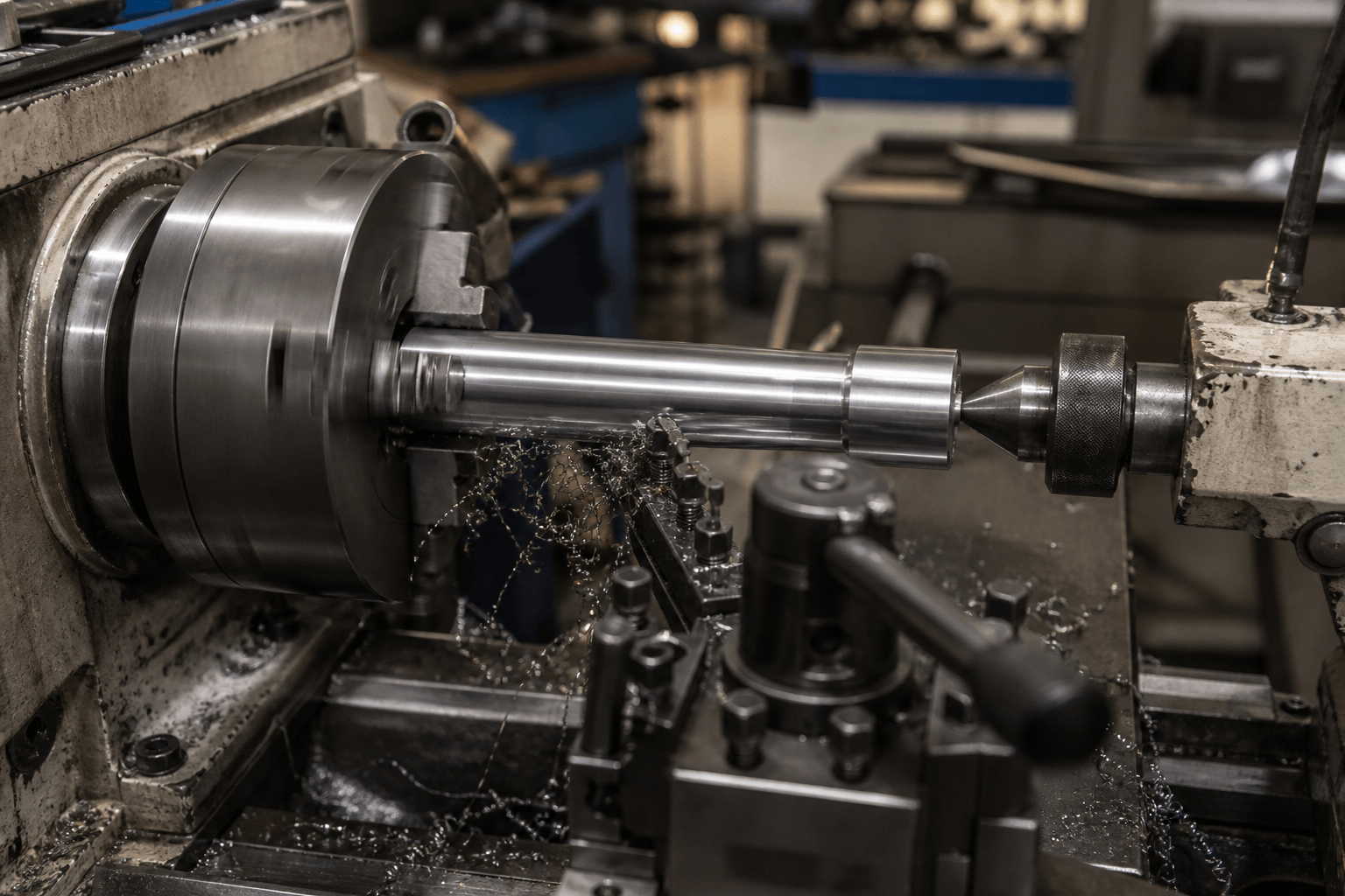
When a drawing calls for a shaft, stepped pin, bushing, threaded stud, or similar rotational part, a metal cutting lathe is often a suitable starting process. The spindle rotates the workpiece about its axis while a cutting tool moves relative to that axis and removes chips. This division of motion makes the lathe well suited to outside diameters, end faces, bores, grooves, tapers, and threads.
If you are deciding between a manual lathe, CNC turning, milling, or a separate fabrication route, start with the part geometry and drawing rather than the machine label. This guide covers machine fit, workholding, source-based cutting-data selection, safe setup, and defect diagnosis. It focuses on metal-cutting lathes and turning workflow; off-axis holes, flats, keyways, complex prismatic features, and formed sheet-metal parts generally need another process.
Where a metal cutting lathe fits—and where it does not
At the quoting or process-planning stage, separate the dimensions generated around a common axis from features added afterward. That distinction affects routing, tooling, inspection datums, and whether the part can be completed in one setup.
| Feature category | Typical tool movement | Practical boundary |
|---|---|---|
| Outside diameter | Tool travels along the spindle axis | Suitable for shafts, steps, shoulders, and turned diameters |
| End face | Tool moves across the end of the stock | Used to establish a flat end or shoulder |
| Bore | A drill or boring tool works along the axis | Requires internal access, bar clearance, and adequate support |
| Groove or recess | A narrow tool feeds into the work | Tool width, depth, chip evacuation, and rigidity matter |
| Taper | The tool follows an angled path | Method depends on taper length, angle, and machine configuration |
| Thread | Tool advances in synchronization with spindle rotation | Pitch, tool geometry, control method, and runout must be verified |
A lathe can produce the turned portion of a part that later receives a flat, keyway, or off-axis hole, but those added features are outside the normal turning boundary. Milling or custom CNC machining is generally more appropriate for those features and for complex non-axis-symmetric geometry. Enclosures, panels, brackets, and frames are not primarily turned parts; review them through a custom sheet metal fabrication route.
Check the machine envelope against the part
At an early sourcing or process-review stage, translate the machine’s headline capacity into the actual setup. A part may fit the nominal swing yet fail to clear the chuck, tool, tailstock, carriage, guard, or bed once stickout and workholding are included.
| Specification to check | What it determines | Question for the target part |
|---|---|---|
| Maximum swing and diameter over the cross slide | Clearance around the rotating work | Will raw and finished diameters clear the bed, chuck, tool, guard, and carriage? |
| Usable work length and distance between centers | Axial envelope and support arrangement | Is there room for chuck engagement, facing allowance, tool travel, and tailstock support? |
| Spindle through-bore | Whether bar stock can pass through the spindle | Can the stock diameter and bar-end clearance pass safely? |
| Chuck or collet capacity | Gripping range and jaw engagement | Is the workholding suitable for the stock shape and material? |
| Speed range and drive behavior | Whether the required cutting speed is within machine limits | Are the low- and high-speed limits suitable for the diameter and tool data? |
| Rigidity and available power | Resistance to deflection, vibration, and overload | Can the setup support the overhang, material, interrupted cut, and intended depth of cut? |
| Tailstock travel and alignment | Free-end support and axial tool access | Can the tailstock reach the support or drilling position without interfering with the feature? |
| Tool post or turret and tooling | Tool access, orientation, and repeatable changes | Can the required turning, boring, grooving, or threading tools reach the feature? |
| Guarding, controls, and electrical service | Installation and operating compatibility | Do the machine manual, site supply, protection, phase, and control requirements agree? |
A manual metal lathe can suit varied parts, prototypes, repair work, and lower-quantity jobs where the operator controls each movement. A CNC turning machine uses programmed tool motion and may suit repeat production or several programmed cycles, but it adds requirements for programming, work offsets, tool setting, simulation or a controlled dry run, and first-run verification.
Neither machine type is universally best. Consider part variety, repeat quantity, feature sequence, operator involvement, required consistency, and the time available for programming and setup. For an early machine-fit review, confirm the stock form, unsupported length, tailstock travel, tool clearance, chuck condition, guarding, and electrical information in the specific machine documentation.
Workholding sets the starting stability
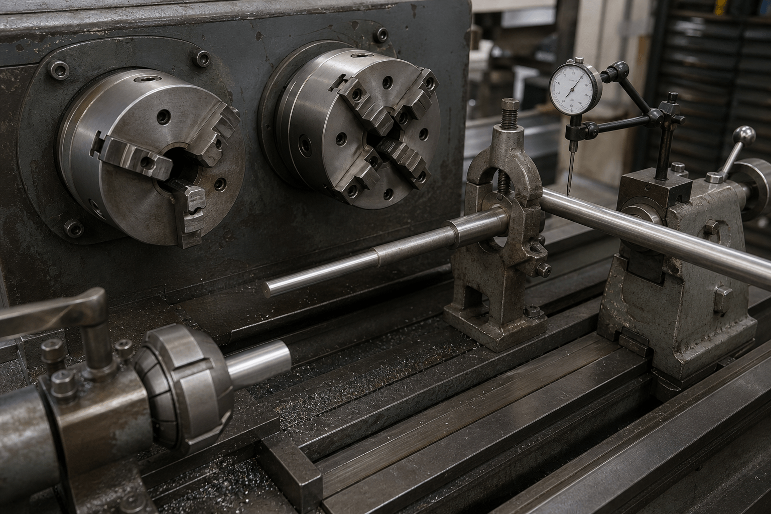
For a prototype or first-piece job, a chuck that appears to fit the stock can still produce excessive runout or vibration if the contact surfaces are dirty or the unsupported length is too great. Workholding also controls the risk of workpiece movement or ejection, so it belongs in the cutting plan rather than being treated as an accessory choice.
| Method | Useful when | Limit or check |
|---|---|---|
| Three-jaw self-centering chuck | Round or hexagonal stock and efficient repeat setups | Centering adjustment is limited; verify jaw engagement and runout |
| Four-jaw independent chuck | Irregular stock or indicator-based alignment | Each jaw requires adjustment; an offset setup may require a balance review |
| Collet | Supported stock sizes and short, repeatable gripping | Capacity is range-specific; clean the collet, nose, and stock carefully |
| Centers | Long shafts needing support at both ends | Center holes, tailstock alignment, lubrication, and a suitable drive method matter |
| Steady or follower rest | Long, slender work that may deflect under the tool | Set contact and clearance correctly; poor adjustment can mark or destabilize the part |
Use a dial indicator or test indicator to check runout at the relevant datum, then align the workpiece to the drawing and machine requirements. There is no universal acceptable runout value: the limit depends on part function, measurement location, operation, and specification. For an asymmetrical or offset setup, check balance and chuck limits under the applicable machine procedure before rotation.
- Clean the chuck jaws, collet, centers, and workpiece contact areas.
- Confirm adequate jaw engagement and tighten using the approved method; remove the chuck key immediately.
- Keep unsupported stickout as short as the feature allows, and add tailstock or rest support when needed.
- Check tool, workpiece, chuck, tailstock, and guard clearance throughout the intended movement.
- Keep people away from the rotation plane and never reach toward moving chips or stock.
Select cutting data from verified tool information
At first-piece stage, a cutting-speed number without the material, tool grade, geometry, operation, and machine condition is not a reliable setting. Obtain starting values from the toolmaker or insert supplier for the actual workpiece material and hardness, then account for rigidity, interrupted cuts, unsupported length, chip control, heat, and coolant or lubrication practice where applicable.
Spindle speed: n = 1000Vc / (πD)
Feed rate: vf = fn × n
Turning depth of cut: ap = (Dstart − Dfinal) / 2
In these relationships, n is spindle speed in rpm, Vc is cutting speed in m/min, D is the cutting diameter in mm, vf is feed in mm/min, and fn is feed per revolution in mm/rev. The depth-of-cut formula gives radial depth; the diameter reduction is twice that value.
Illustrative calculation only: If verified tool data allowed Vc = 120 m/min at a 40 mm cutting diameter, the calculated speed would be about 955 rpm. If the same data specified fn = 0.12 mm/rev, the feed rate would be about 115 mm/min. These figures demonstrate the calculation method, not recommended settings; check the selected tool, material, machine, and operation before use.
A useful turning-parameter worksheet records the material and hardness, insert grade and nose geometry, operation type, source of the recommended speed and feed, cutting diameter, stock allowance, radial depth, support condition, and the adjustment made after the first cut. If vibration, heat, chip-control problems, tool wear, or an interrupted cut appears, improve support or revisit the validated data conditionally. Where the procedure permits, change one significant variable at a time and record the result.
A controlled sequence from drawing to first piece
Before the first chip is made, connect the drawing requirements to the physical setup and the machine procedure. A controlled sequence reduces avoidable surprises, but it does not replace the machine manual, site risk assessment, guarding, or operator training.
- Review the drawing. Mark datums, finished diameters, lengths, threads, bores, runout requirements, surface notes, stock allowance, and inspection points. Confirm the material and locate the applicable tool data.
- Inspect the machine. Check guarding, controls, tool condition, chuck condition, lubrication indicators or other machine-manual requirements, and the work area before energizing.
- Secure the workpiece. Select the chuck, collet, centers, or rest; clean the contact surfaces; control stickout; and verify runout and balance as applicable. Remove the chuck key before any rotation.
- Set the tool. Check tool height, orientation, insert condition, clamping, and access to the feature. Incorrect height can affect facing, diameter, vibration, and tool load.
- Confirm the cut. Select source-based speed, feed, and depth of cut. Check spindle direction, clearance, guard position, and the intended approach and withdrawal path.
- Complete the machine-specific preflight. On a CNC turning machine, review the program, offsets, tool numbers, and simulation or controlled dry-run procedure where applicable. On a manual machine, confirm the handwheel or power-feed sequence and stopping points.
- Make the cut. Start with the approved procedure and monitor chip form, noise, vibration, heat, surface condition, and tool-edge condition. Stop if the work shifts, the tool interferes, or abnormal noise or vibration develops.
- Measure only after stopping. Retract the tool, stop spindle rotation, wait for the work to stop, and measure the required feature with a suitable verified instrument. Account for part temperature and use the same datum identified on the drawing.
- Remove chips and close the job. Use a brush or chip hook only after rotation has stopped; never pull chips by hand. At shutdown, follow the machine and site procedure, clean the area, inspect the first piece, and record findings before repeat production.
Diagnose defects by checking measurement and setup
An out-of-specification first piece can create pressure to change speed or feed immediately. Verify the measurement and setup first: confirm that the instrument is suitable and verified, the datum is correct, the part has stopped and reached a stable temperature, the measurement location is repeatable, and the reading can be reproduced.
| Symptom | Likely checks | Conditional corrective action |
|---|---|---|
| Chatter or visible vibration | Workpiece or tool overhang, weak support, loose workholding, rigidity, speed, feed, and tool geometry | Improve support, shorten overhang, secure the setup, and revisit validated data one change at a time |
| Tapered diameter | Workpiece deflection, tailstock alignment, tool wear, runout, or changing support | Measure both ends from the same datum; align, support, or replace tooling as indicated |
| Inconsistent size | Thermal movement, insert wear, handwheel variation, loose setup, or measurement error | Repeat the measurement at a stable temperature and check tool condition, setup security, and compensation method |
| Center residue after facing | Tool height or orientation, edge condition, and whether the tool reached true center | Correct the tool setting and verify the facing path; do not assume speed alone is the cause |
| Rough or changing surface | Chatter, dull edge, built-up edge, unsuitable feed, material condition, or poor support | Inspect the edge, improve rigidity, and select geometry and data for the actual material and operation |
| Burrs | Tool wear, exit condition, sharp edges, and feed direction | Review tool condition and edge treatment, then apply a controlled deburring step if specified |
| Tool damage or breakage | Collision, incorrect height, excessive load, interrupted cut, loose workholding, or chip packing | Stop, inspect the complete setup, replace damaged tooling, and revalidate the cutting conditions |
| Runout or eccentricity | Chuck or collet contact, jaw condition, alignment, stock balance, and datum choice | Clean and reset workholding, indicate the required surface, and compare the result with the drawing requirement |
For repeat work, keep a first-piece record showing the setup, tool identification, measured diameters and lengths, runout or surface observations, and any approved adjustment. A documented inspection approach, such as the one described in quality control, helps separate measurement variation from a genuine process problem.
Frequently Asked Questions
These questions commonly arise when a prototype drawing or production RFQ includes both turned dimensions and features that may require another process. Use the answers as a screening guide, then verify the final route against the drawing, tolerances, quantity, finish, and machine documentation.
What is a metal cutting lathe used to make, and which features are outside its practical scope?
It is used mainly for rotational features such as outside diameters, faces, bores, grooves, tapers, and threads. Off-axis holes, flats, keyways, and complex non-axis-symmetric shapes generally need milling or broader CNC machining, while enclosures and formed panels belong to sheet metal fabrication.
What is a good beginner metal lathe?
Choose by usable swing, work length, spindle through-bore, chuck capacity, rigidity, speed control, guarding, documentation, controls, electrical compatibility, and support. For prototype work, also compare the machine’s usable capacity with the drawing tolerances, finish requirements, and expected quantity rather than relying on a model name.
What is the first step before using a metal cutting lathe?
Review the drawing and process plan, then inspect the machine and work area. Before rotation, confirm secure workholding, adequate clearance, correct tooling and tool height, and chuck-key removal.
How do you calculate spindle speed on a metal cutting lathe?
Use n = 1000Vc / (πD), with cutting speed in m/min, diameter in mm, and spindle speed in rpm. Obtain Vc from the toolmaker or insert data for the actual material, tool, operation, and machine condition before applying the result.
Why does a lathe produce chatter, taper, inconsistent dimensions, or a poor surface finish?
Common causes include weak workholding, excessive overhang, deflection, incorrect tool height, runout, tool wear, thermal movement, and unsuitable cutting data. Verify the instrument, datum, part temperature, and setup first, then correct the condition or change validated parameters conditionally.