
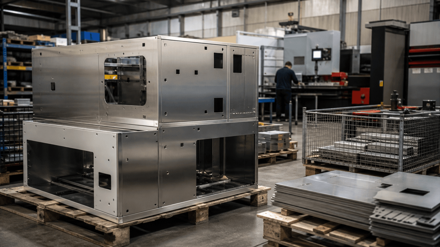
For an OEM, “metal manufacturing” does not name one machine or one supplier capability. It is the broader conversion of metal materials or semifinished stock into industrial components, assemblies, and finished products, using operations such as cutting, forming, machining, joining, finishing, assembly, and inspection.
Direct answer: Sheet-metal fabrication is one downstream route within metal manufacturing, not a synonym for the whole field. An OEM route is usually narrowed by stock form—sheet, plate, tube, solid stock, billet, or molten metal—together with geometry, material grade or series, state where relevant, thickness, tolerances, quantity, finish, and assembly interfaces.
That distinction matters when an OEM moves from a concept or prototype toward a repeatable product. An enclosure, frame, or welded assembly may fit a sheet-metal route, while a solid interface part, cast shape, or constant-section rail may point to another process family or a combination of several.
Metal manufacturing covers more than fabrication
When a buyer describes a project as “metal manufacturing,” the first question is whether the requirement concerns feedstock production or the finished product. For most OEM sourcing decisions in this guide, the relevant work begins after the material has been supplied in a usable form. That boundary prevents a fabrication quote from being compared with an upstream metalmaking operation or with a process intended for a different geometry.
Upstream metal production includes mining, smelting, refining, and related operations that create or prepare metal feedstock. Downstream manufacturers buy sheet, plate, tube, bar, billet, or other semifinished forms and convert them into brackets, cabinets, guards, frames, and equipment components. The two areas are connected, but they involve different inputs, equipment, decisions, and commercial questions.
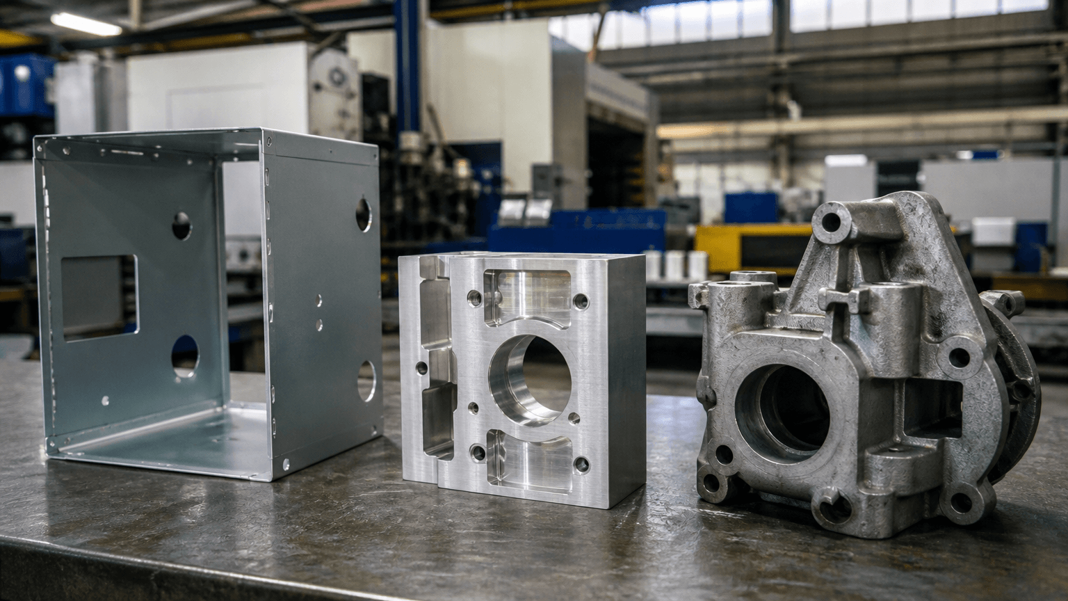
Sheet-metal fabrication is one downstream route, commonly using sheet, plate, tube, or related sections. It may combine laser cutting, CNC punching, bending, welding, finishing, and assembly, whereas machining removes material from solid or near-solid stock, casting shapes molten metal in a mold, and extrusion forces a billet through a die. Stamping and deep drawing form sheet or strip with dedicated tooling. Industry classifications vary, so no universal list of only three metal-manufacturing types applies to every project.
Choose the route from stock form and geometry
Suppose an OEM concept starts as a cabinet, frame, or flat mounting component. If the design is built from sheet or plate and depends on cutouts, flanges, and joined panels, fabrication is a logical route to examine first; if it requires a solid block, a molded cavity, or a constant profile, another family may be more suitable. The matrix below is directional because drawing-based DFM, material availability, quantity, and supplier capability still determine the final choice.
Directional route-selection matrix: stock form, geometry, quantity, and finishing needs
| Stock form and geometry | Dominant process family | Typical product situation | Quantity and setup signal | Finish and assembly checks |
|---|---|---|---|---|
| Sheet or plate with flat profiles and bends | Laser cutting or CNC punching, followed by bending; welding when separate parts must be joined | Enclosures, cabinets, panels, brackets, and frames | Changing profiles favor flexible blanking; repeated features, nesting, setup, and quantity affect the route review | Bend relief, hole access, joint access, coating masks, and mating clearances |
| Tube or structural section | Cutting, drilling or punching, bending, and welding | Equipment frames, racks, supports, and guards | Section orientation, fixtures, joint repeatability, and handling influence the process plan | Weld access, coating coverage, assembly datums, and protective packaging |
| Solid bar or near-solid stock | Machining, such as turning or milling | Shafts, blocks, housings, and machined interface features | Stock removal, workholding, setup, and inspection references dominate the route | Machined interfaces remain distinct from fabricated panels and require defined mating conditions |
| Molten metal | Casting in a mold | Cast shapes with cavities or integrated features suited to a molded form | Mold design, tooling commitment, material behavior, and expected quantity must be weighed together | Draft, parting considerations, surface condition, and downstream interfaces |
| Billet for a continuous profile | Extrusion through a die | Rails, channels, and profiles with a consistent cross-section | Die design is tied to the profile and creates different setup assumptions from cutting and bending | Cut-to-length operations, secondary holes, joining, coating, and assembly clearances |
| Sheet or strip with dedicated dies | Stamping, deep drawing, or another dedicated forming route | Repeated shells, drawn shapes, and formed components | Tooling, draw behavior, springback, setup, and expected volume may outweigh a flexible route | Trimmed edges, surface appearance, forming marks, finish, and fit |
Laser cutting separates material thermally along a programmed profile. It suits changing contours, openings, and flat components, and may be paired with bending when a blank must become a three-dimensional panel; laser cutting for sheet-metal profiles, openings, and flat components is one example of that route. CNC punching uses a mechanical punch-and-die action to create holes, cut features, or selected formed details. Repeated patterns, tool access, feature geometry, material, quantity, and finish should be considered rather than treating laser cutting and punching as interchangeable.
Bending plastically deforms sheet or plate to create flanges, channels, brackets, and enclosure panels; unlike machining, it does not remove material. Metal bending for formed panels, brackets, and enclosures must account for bend allowance, bend sequence, springback, and tool access. Welding joins separate components using heat and, where applicable, filler material, so welding for joined sheet-metal parts and fabricated assemblies addresses a different need from cutting or bending.
Many products use more than one process family. A sheet-metal enclosure, for example, may include a separately machined interface block or insert; the panel and insert retain their own process requirements, while the assembled fit depends on shared datums, hole or fastener arrangements, clearances, and assembly sequence. The complete product should therefore not be labeled entirely machined or entirely fabricated.
Early route check: If the product aligns with the sheet or plate route, an early review of custom sheet-metal structures and welded assemblies can help test the initial process assumption before a formal quotation. The matrix is a screening tool, not a substitute for a drawing-based DFM review or supplier capability confirmation.
Requirements that narrow the process choice
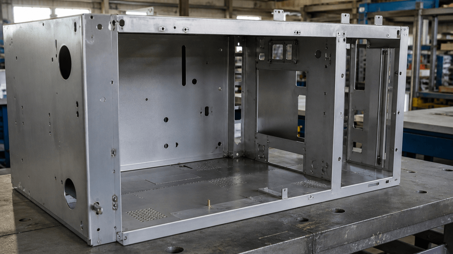
Once the stock form points toward a route, the buyer needs to define what the part must do and how it must fit. A cabinet exposed to moisture, a visible display rack, and an internal equipment bracket may all use sheet metal but require different material, joint, tolerance, and finish decisions. Leaving those inputs vague can force the supplier to make assumptions after the design is already frozen.
| Requirement | Route-selection consequence |
|---|---|
| Function and service environment | Load, stiffness, temperature, moisture, corrosion exposure, and visible surfaces influence material and construction choices. |
| Material grade, state, and thickness | Specify the grade or series, state where relevant, and thickness—not only steel or aluminum. These inputs affect forming response, welding behavior, weight, finish, and material availability. |
| Geometry and forming | Define the inside bend radius, bend-allowance method or K-factor, minimum flange, springback expectations, and hole-to-bend-line distance. |
| Datums and tolerances | Identify assembly datums, critical dimensions, tolerance zones, and inspection references. A visually acceptable fit does not replace a defined functional requirement. |
| Joining details | Weld symbols, weld length, joint type, grinding level, fixture access, and visible-weld expectations can change sequence and labor. |
| Surface finish | State pretreatment, powder-coat color or texture, film build, masking areas, corrosion expectations, and acceptable appearance. Finish build can affect holes, threads, and mating surfaces. |
| Quantity and design maturity | Prototype quantity, expected repeat volume, revision stability, setup effort, tooling, nesting, and fixture investment should be considered together. |
| Assembly and packaging | Fastener access, part orientation, service access, clearance, protective packaging, and shipping constraints can influence the operation sequence. |
These requirements shape qualitative cost and lead-time trade-offs. A flexible route can limit upfront tooling commitment, while a stable repeat program may justify more setup, fixtures, or dedicated tooling; nesting affects material utilization, and inspection or protective packaging adds work. Repeatability, rework exposure, and change-control effort matter alongside the nominal operation, so no process family is automatically the lowest-cost or fastest choice for every geometry.
The critical handoffs are between operations
The route is not finished when a profile is cut. Fit and consistency risks often appear at the handoff between operations, where a flat pattern becomes a formed part, a welded joint becomes a finished surface, or a coated component enters assembly. Reviewing these transitions as a connected map is more useful than reviewing cutting, bending, welding, finishing, and assembly as isolated steps.
- Model to flat pattern: Translate the formed model into a cut pattern using bend compensation, bend allowance or K-factor, material direction where relevant, corner relief, and suitable hole-to-bend placement. A feature that appears correct in the flat state can interfere with a flange or shift relative to a datum after forming.
- Cutting to bending: Cut features become references for forming. Bend order, tool access, part orientation, and springback compensation influence flange position and the relationship between holes, edges, and datums, so dimensions that matter after bending should be reviewed rather than checking only the blank.
- Bending to welding: Flanges and separate components must permit joint access and fixturing. Weld heat can distort the assembly, making joint design, fixture control, weld sequence, grinding requirements, and inspection of key dimensions part of the same review.
- Welding to finishing: Weld profiles, spatter, sharp edges, and the specified grinding level affect surface preparation and appearance. Masking may be needed around threads, holes, grounding points, or mating surfaces, while coating build can reduce clearance when the design does not allow for it.
- Finishing to assembly and packaging: Finished parts need usable datums, accessible fasteners, correct orientation, and enough clearance for installation. If a machined component is installed in a fabricated assembly, its drawing and the shared interface dimensions should remain clear; packaging should prevent scratches, edge damage, movement, and contact between visible surfaces.
Not every product uses every operation, and the release package should distinguish required steps from optional appearance or convenience work. A flat laser-cut plate may need no bending or welding, while a cabinet may require cutting, bending, joining, coating, and assembly; the drawing should make those differences visible before production starts.
Prototype approval and batch readiness are different decisions
Prototype approval answers whether the design can work; batch readiness asks whether the approved design can be repeated under controlled conditions. A prototype review can expose fit, bend, weld, finish, and assembly issues while changes are still manageable, but a visually acceptable sample does not by itself prove batch consistency.
| Decision area | Prototype emphasis | Batch-production emphasis |
|---|---|---|
| Objective | Confirm function, fit, appearance, and the practical interpretation of the drawing. | Repeat the approved design consistently across units. |
| Setup and tooling | Flexible setup and design learning may take priority. | Fixtures, stable references, and suitable tooling may justify more preparation. |
| Material utilization | Nesting may remain provisional while the design changes. | Nesting, remnant use, and blank organization affect utilization and scheduling. |
| Inspection and change control | Discover critical dimensions, fit risks, and unclear drawing requirements. | Define inspection points, revision control, records, and responses to nonconformance. |
| Finish and packaging | Confirm color, texture, masking, appearance, and handling expectations. | Control preparation, coating appearance, protection, labeling, and packing consistency. |
The process family may remain the same even when the production method changes. A prototype may favor flexible blanking and setup, while repeat production may justify a revised nesting plan, fixtures, or a different blanking or forming approach. Setup effort, tooling, order quantity, rework exposure, inspection, packaging, and change control all affect the commercial result.
OEM products suited to custom sheet-metal routes
Custom sheet-metal manufacturing is worth evaluating when the product envelope, openings, mounting features, formed panels, and structural joints can be created from cut and formed stock. This often includes enclosures, cabinets, frames, display racks, welded assemblies, and laser-cut or bent components; fit still depends on the drawing, finish, tolerances, and assembly interfaces.
Enclosures and cabinets: Laser-cut or punched panels can provide openings, mounting points, ventilation features, and access-door details before bending and joining. Internal component clearance, cover alignment, fastener access, visible surfaces, masking, and service access should be reviewed together.
Frames and display racks: These products may combine formed brackets, sheet panels, tube or section members, and welded joints. Load paths, joint access, fixture datums, coating coverage, and packaging protection can influence the route more than the cutting operation alone.
Welded assemblies: A fabricated assembly may use multiple laser-cut or punched parts, locating flanges made by bending, and fixtures to support the weld sequence. Distortion control, grinding level, appearance requirements, and key-dimension inspection should be agreed before production.
Laser-cut and bent components: Brackets, mounting plates, covers, supports, and formed panels may suit a route that combines flat features with three-dimensional stiffness. That does not mean a cast mold or extrusion die is necessary for every such component; the geometry and quantity still need review.
Yishang’s stated custom sheet-metal scope includes laser cutting, CNC punching, bending, welding, powder coating, polishing, assembly, prototype review, and batch production. It supports B2B wholesale, OEM, and ODM custom manufacturing projects, has more than 26 years of experience, and exports to more than 50 countries. This company context does not confirm the fit of a particular product; that still requires a drawing-based review.
FAQs for OEM metal manufacturing decisions
These questions address common route decisions before an OEM sends drawings for a formal review. They focus on process boundaries, material and finish inputs, and the differences between prototype approval and repeat production.
Is metal manufacturing the same as metal fabrication?
No. Metal manufacturing is the broader conversion of metal materials or semifinished stock into parts, assemblies, and products. Fabrication is one downstream subset, commonly involving cutting, forming, joining, finishing, and assembly of sheet, plate, tube, or sections.
Do machining, casting, and extrusion count as metal manufacturing?
Yes. They are related metal-manufacturing process families with different starting forms and tooling assumptions. Machining removes material from solid stock, casting shapes molten metal in a mold, and extrusion pushes billet through a die.
Are laser cutting and CNC punching interchangeable for sheet metal?
No. Both can create sheet-metal cut features, but laser cutting uses thermal separation while punching uses a punch-and-die action. Feature geometry, repeated patterns, tooling, material, quantity, and finish requirements determine the suitable choice.
Why can material grade, thickness, and surface finish change the route?
Grade and state can affect forming and welding behavior, while thickness changes bending and joining conditions. Pretreatment, coating build, masking, corrosion expectations, and appearance can also affect holes, threads, clearances, and final assembly fit.
Can a prototype and a batch use different metal manufacturing routes?
They can. A prototype may favor flexible setup, while batch production may benefit from nesting, fixtures, tooling, defined inspection points, and stronger change control. The process family may stay similar even when the production method changes.
Evaluating an OEM or ODM metal manufacturing project? For a route-fit review, send a 2D drawing, 3D model, or product sketch if available, together with the material grade or series, state where relevant, thickness, product function, service environment, critical assembly interfaces, prototype or batch intent, expected quantity, required finish, color or texture, masking areas, and inspection expectations. Yishang can review whether the product fits its custom sheet-metal workflow of laser cutting, CNC punching, bending, welding, finishing, and assembly, helping identify route or specification gaps before a formal quotation.