
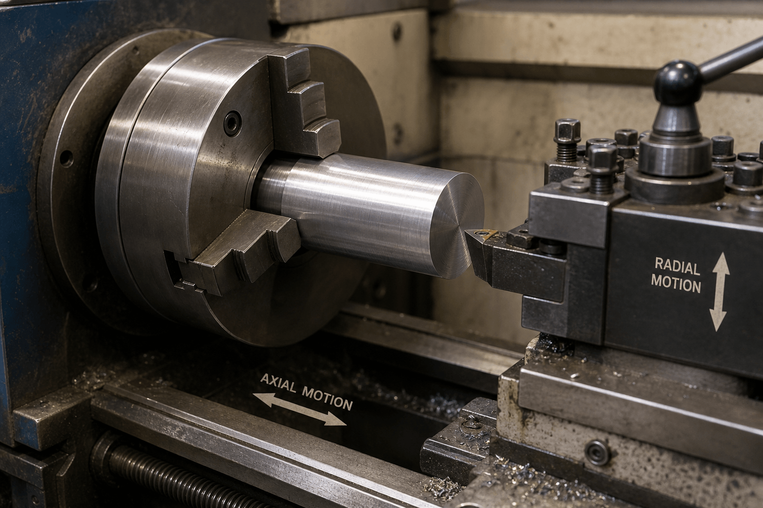
Answer: Operations on a lathe machine create mainly rotational features by rotating the workpiece while a controlled cutting tool removes material. External turning, facing, taper turning, grooving, parting, threading, drilling, boring and reaming produce different diameters, faces, recesses, threads and bores; conventional knurling forms a grip pattern by displacing material rather than by ordinary chip removal.
Start with the drawing geometry. Use a lathe when the required surfaces are organized around a spindle axis, such as outside diameters, shoulders, end faces, tapers, grooves, threads and concentric bores. Workholding, material, tool selection, machine rigidity and inspection requirements then determine the practical setup. Flats, slots, cross-holes and other non-rotational features may require milling, live tooling, turn-mill equipment or a separate process.
Start with the Required Part Geometry
When reviewing a shaft, pin, spacer, sleeve or threaded stud for manufacture, identify which dimensions are generated by rotation and which are not. A turned diameter is produced as the cutting edge travels along the spindle axis; a face is produced by radial travel across the end; and an angled tool path produces a taper. A stepped shaft, for example, may need straight turning for its diameters, facing for its end datum, grooving for a retaining-ring relief and threading for an external connection. A sleeve may require drilling, boring and reaming in addition to external turning.
If the same part includes a keyway, flat or off-center hole, transferring it to milling or using a turn-mill machine may be necessary. Manual and CNC lathes use the same fundamental operations, but manual machines depend on direct operator control while CNC machines coordinate programmed movements, offsets and repeated tool paths. Not every lathe can perform every listed operation. Machine swing, spindle bore, speed range, torque, tooling, turret, tailstock and live-tool capability must suit the drawing. Turning is also distinct from sheet metal fabrication, welding, finishing, assembly and inspection. A part primarily cut and formed from sheet belongs to a different process family; see custom sheet metal fabrication.
External Operations: What Each One Produces
For process selection, the important distinction is the feature left on the part: a diameter, shoulder, datum face, taper, relief, cutoff surface, thread or grip pattern. Roughing removes stock within the limits of the setup; finishing removes the remaining allowance under conditions selected for the required size and surface finish.
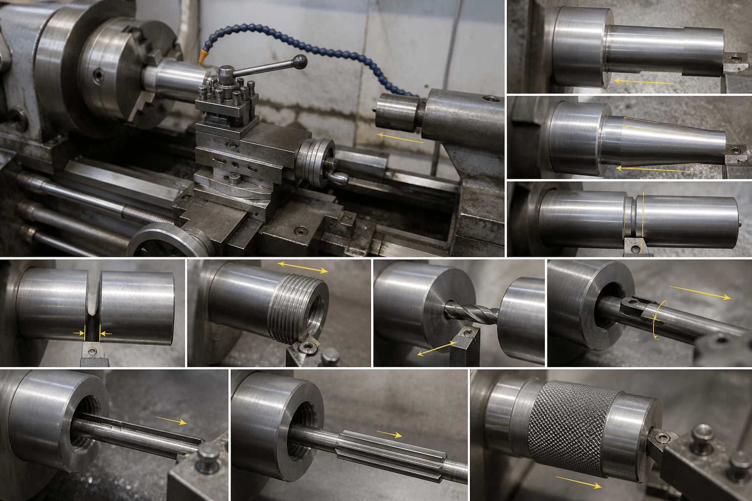
- Straight turning: The tool travels mainly parallel to the spindle axis and produces a cylindrical outside diameter.
- Step turning: Separate axial sections are turned to different diameters, creating steps and shoulders that may locate bearings, seals or mating parts.
- Facing: The tool travels radially across the workpiece end to produce a flat face, establish an axial datum or set a finished length.
- Taper turning: The tool follows an angled or coordinated axial-radial path to produce a conical surface. Inspection must follow how the drawing defines the taper.
- Chamfering: A short angled cut removes a sharp edge at an end, shoulder, hole or thread entrance. Chamfer size and angle remain drawing-controlled features.
- Grooving: A narrow tool plunges radially to create an external or internal recess, such as a retaining-ring groove or thread relief.
- Parting off: A thin blade feeds radially through the stock until the component separates. Unlike grooving, the objective is complete cutoff.
- Threading: A single-point tool moves axially in synchronization with spindle rotation to generate a specified pitch and profile. Dies can produce or finish some external threads but are not interchangeable with single-point threading for every material, diameter or tolerance.
- Knurling: Wheels press against the rotating workpiece to form a straight, diagonal or diamond pattern. The wheels displace material, so blank diameter, ductility, alignment, force and rigidity affect the resulting profile and diameter.
Hole-Making and Internal Features
A drilled hole is not automatically a finished or accurately located bore. The required location, diameter, alignment, surface condition and fit determine whether drilling is sufficient or whether boring, reaming, internal grooving or internal threading is required.
| Operation | Result | Movement and main concern |
|---|---|---|
| Center drilling | Creates a short starting feature for a drill or a center feature for supported work. | Axial feed; verify alignment, depth and center form. |
| Drilling | Originates an axial hole with a suitable drill. | Axial feed from a tailstock or turret; control runout, depth, alignment and chips. |
| Boring | Enlarges an existing hole and can correct diameter or improve its relationship to the spindle axis. | A single-point boring bar travels axially; overhang, deflection and clearance are critical. |
| Reaming | Finishes a suitably prepared hole to a specified size and surface condition. | Axial feed through an aligned hole with a controlled allowance; it cannot correct every location error. |
| Internal grooving | Creates a recess or relief inside a bore. | A narrow tool plunges radially; visibility, wall clearance and chip removal are limited. |
| Internal threading | Produces a thread inside a drilled or bored hole. | Synchronized axial travel; provide entry, relief, chip space and withdrawal clearance. |
Drills can deflect, follow an imperfect starting surface, cut larger than nominal or leave a surface unsuitable for a close fit. Boring may correct size and improve coaxiality, while reaming finishes a hole that already has suitable alignment and machining allowance. Shortest-practical boring-bar overhang, adequate wall and bottom clearance, and planned chip evacuation are especially important for internal work.
Secure the Setup Before Cutting
Setup decisions affect both safety and the accuracy available from the operation. A three-jaw chuck offers quick gripping for many round or hexagonal blanks. An independently adjustable four-jaw chuck allows a selected feature to be indicated into position. A compatible collet provides distributed contact on suitable bar or small round stock. Faceplates can hold unusual shapes with an appropriate secure fixture, while centers support long work along the spindle axis and steady rests support work near the cutting area when unsupported length could cause deflection.
Clean jaws, collets, center holes and locating surfaces before clamping. Use an indicator to check radial runout and, where relevant, axial face runout. Keep workpiece and tool overhang as short as the geometry permits. Set the tool tip at spindle center height; incorrect height changes cutting geometry and can cause rubbing, vibration or a center nib after facing.
- Confirm secure clamping and remove the chuck key.
- Check clearance from jaws, chuck, centers, tailstock, steady rest, shoulders and finished surfaces.
- Verify spindle direction, tool travel, guards and emergency-stop access.
- Confirm internal tools clear the bore wall, shoulder and blind-hole bottom.
- Use a controlled first cut or program prove-out after setup or offset changes.
Select Cutting Conditions by Operation and Material
Cutting conditions must match the workpiece material, tool material and geometry, machine rigidity, workholding and required finish. Cutting speed is the surface velocity at the tool; spindle speed is revolutions per minute. In metric units, the approximate relationship is n = 1000V/(πD), where V is cutting speed in metres per minute, D is diameter in millimetres and n is rpm. Feed is commonly specified per revolution, while depth of cut is radial stock removed in one pass; the approximate diameter change is twice the radial depth.
Use current tooling-manufacturer data for the actual alloy, tool grade, operation and diameter rather than a universal table. High-speed steel may suit some manual, low-speed or specially ground tools; carbide often supports higher speeds when rigidity is adequate. Nose radius, rake, chip-breaker geometry, interrupted cuts, power, torque and desired finish all affect the choice. Coolant, cutting fluid, dry machining or air should follow material and tooling guidance, heat, lubrication and chip-evacuation needs. Internal turning, parting and threading normally require additional attention to clearance and chip control because the tool has less room to evacuate chips.
Inspect the Feature and Diagnose Defects
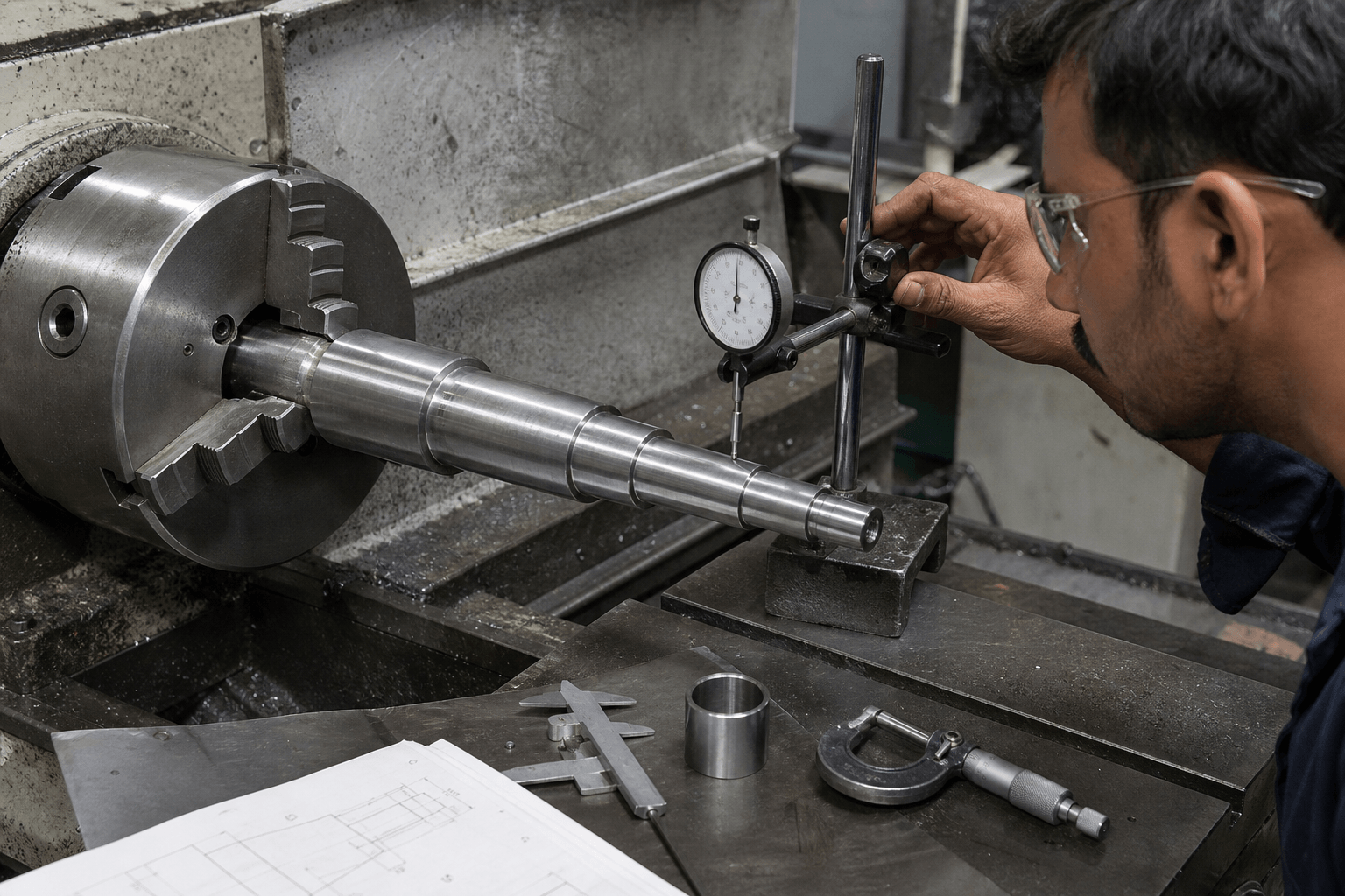
Plan inspection from the drawing. In-process checks help identify wear or dimensional drift before more parts are affected; final inspection verifies the stated acceptance criteria. Use a micrometer for close outside diameters, calipers or suitable length instruments for general dimensions, a bore gauge or internal micrometer for bores, and an indicator for runout. Threads may require thread micrometers, pitch checks, plug or ring gauges, or another drawing-specified method. Use a suitable taper check for tapers and a surface-finish instrument when a numerical finish requirement applies. The drawing determines the required inspection method and acceptance criteria. For inspection-planning context, see quality control.
| Symptom | Checks to make first |
|---|---|
| Chatter or repeating marks | Check clamping, overhang, support, tool height, insert condition and rigidity, then review speed, feed, depth and nose radius. |
| Built-up edge | Check that the tool cuts rather than rubs; review sharpness, rake, speed, feed, chip-breaker geometry and fluid guidance. |
| Poor finish or stringy chips | Check vibration, wear, feed, nose radius, chip-breaker suitability, depth of cut and fluid delivery. |
| Taper error | Measure both ends, then check workholding, relevant alignment, deflection, thermal change and uneven stock removal. |
| Dimensional drift or rapid wear | Check temperature, offsets, insert seating, material condition, tool grade, speed, feed, interrupted cuts and chip control. |
| Center nib after facing | Check center height, tool orientation, insert condition, clearance and whether the tool path reaches the spindle axis. |
Verify the measurement method before changing a process. Temperature, burrs, contamination, runout, deflection and inconsistent measuring force can make a machining defect appear to be an inspection defect. Change one cutting variable at a time so its effect can be evaluated safely.
If you are preparing an RFQ or drawing review for a turned or mixed-machined part, submit the part drawing or 3D model together with the material and required condition, quantity, critical dimensions and tolerances, surface-finish requirements, rotational and non-rotational feature identification, assembly interfaces and inspection requirements. Yishang supports B2B OEM and ODM custom manufacturing and can review the geometry with you to discuss a suitable process route without assuming that every feature belongs on a basic lathe.
Select the Operation by Drawing Feature
Use this compact route-planning matrix as a starting point; the machine, tooling, workholding and drawing acceptance criteria determine the final process.
| Feature | Likely operation and movement | Setup concern | Verification |
|---|---|---|---|
| Flat end or controlled length | Facing; radial travel | Center height and axial datum | Length and face runout if specified |
| Reduced diameter or shoulder | Straight or step turning; axial travel | Support and shoulder access | Micrometer and shoulder location |
| Taper | Taper turning; angled travel | Path angle and alignment | Defined diameters and taper method |
| Groove or relief | Grooving; radial plunge | Tool width and chips | Width and depth |
| Cutoff | Parting; radial feed through stock | Blade alignment and support | Length, burr and end face |
| External or internal thread | Threading; synchronized axial travel | Pitch, relief and access | Drawing-specified thread gauge or measurement |
| Initial hole | Center drilling and drilling; axial feed | Alignment, depth and chips | Diameter, depth and location |
| Corrected or finished bore | Boring or reaming; axial feed inside hole | Bar rigidity or prepared allowance | Bore gauge and finish where specified |
| Grip pattern | Knurling; forming-wheel pressure | Blank diameter, force and rigidity | Pattern, diameter and function |
For flats, slots, cross-holes or other non-rotational features, a broader CNC machining route may be more suitable than a basic lathe setup.
Where RFQ Assumptions Create Cost and Production Risk
Many sheet metal fabrication problems begin before production starts. If drawings, tolerances, finish expectations, material grades, or assembly requirements are unclear, suppliers may quote based on different assumptions. That can make prices difficult to compare and may lead to rework, cosmetic rejection, assembly misalignment, or production delays later.
For OEM buyers, the goal is not simply to request the lowest price. The goal is to make sure each supplier is quoting the same manufacturing reality. Before confirming an order, clarify which dimensions are fit-critical, which surfaces are cosmetic, whether prototypes must match batch-production conditions, and how finished parts will be inspected.
Frequently Asked Questions
These questions address common operation and process-selection issues when a part is being reviewed for prototype or repeat-production machining.
What is the difference between turning and facing on a lathe?
Turning removes material from an outside diameter with mainly axial tool travel. Facing moves the tool radially across the end to create a flat face and establish length or an axial reference.
Why is a drilled hole sometimes bored or reamed afterward?
Drilling originates a hole but may not meet its required size, alignment or finish. Boring enlarges or corrects an existing hole; reaming finishes a suitably aligned hole with appropriate allowance.
Can a lathe produce flats, slots or off-center holes?
A conventional lathe mainly produces axisymmetric features. These features generally require milling, live tooling, turn-mill equipment or a separate setup, depending on the machine and drawing.
How do three-jaw chucks, four-jaw chucks and collets affect runout?
Three-jaw chucks provide quick gripping for many round parts, four-jaw chucks permit independent indication, and compatible collets distribute contact on suitable stock. Actual runout depends on condition, cleanliness, contact surfaces and setup technique.
Why does facing sometimes leave a projection at the center?
Incorrect tool center height, orientation, insert condition, clearance or tool travel can leave a center nib. Check each before making another facing pass.