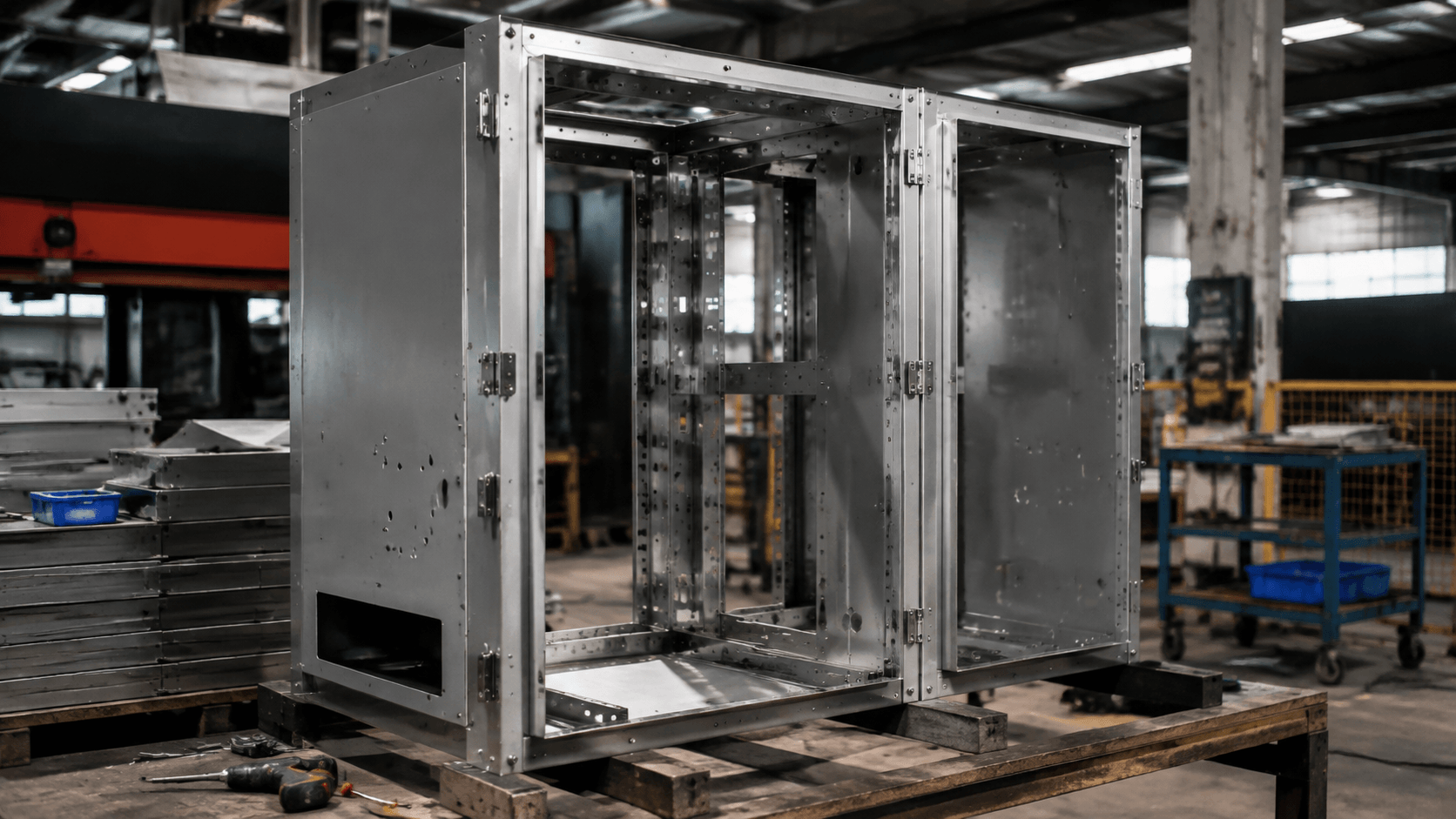
In short: Fabrication assembly coordinates the production of metal components with their joining, fitting, specified hardware installation, and assembly-level verification. Fabrication creates individual sheet metal parts; assembly establishes the relationships among those parts.
Separate laser-cut or CNC-punched panels can become bent parts, a welded or fastened subassembly, and then a finished mechanical enclosure with hinges, latches, brackets, and fasteners. The requested delivery state determines where the factory scope ends and downstream work begins.
That boundary matters for enclosures, cabinets, racks, frames, and welded assemblies. Welding creates permanent joints, finishing changes surface condition, fastening creates removable or retained connections, and inspection verifies defined requirements. These operations support one another, but they do not replace one another.
What Fabrication Assembly Means in a Sheet Metal Project
Fabrication assembly does not have one universal scope. The drawing package, BOM, assembly instructions, and agreed delivery state define whether the supplier provides loose parts, a welded shell, a finished mechanical unit, or mechanical interfaces for customer-installed components.
Component fabrication establishes usable part geometry. Laser cutting and CNC punching create perimeters, holes, and slots. Bending creates flanges and angles. Specified edge preparation can prepare parts for joining.
Welding can create the first assembly-level output, such as an equipment frame or enclosure shell. Welding alone does not create a finished cabinet or rack. Mechanical assembly adds the specified relationships among the shell, doors, panels, brackets, hardware, and other parts.
That work may include fitting doors and panels, installing hinges, latches, handles, feet, threaded hardware, and removable fasteners, then checking the completed mechanical product or subassembly. An enclosure may therefore ship as separate bent panels, a welded shell, or a finished mechanical cabinet.
When the customer supplies electronics or proprietary modules, the manufacturer can work from agreed envelope dimensions, mounting patterns, openings, and clearances. That mechanical preparation does not automatically include wiring, electronics installation, commissioning, or downstream functional testing. See Yishang’s Assembly service and its page on custom sheet metal structures and assemblies for related scope.
Where Fabrication Ends—and Assembly Begins
The clearest boundary comes from the output and assigned responsibility, not only from the machine or joining method. Several stages can appear in one route while keeping different purposes.
| Stage | Typical work | Output and scope boundary |
|---|---|---|
| Sheet metal component fabrication | Laser cutting, CNC punching, hole and slot creation, bending, and specified edge work | Separate sheet metal parts such as panels, doors, brackets, or rails. |
| Welded fabrication | Fixturing, tacking, welding, and grinding or polishing where specified | A permanent frame, shell, or welded subassembly. Welding creates a joint, not the entire mechanical assembly. |
| Surface finishing | Surface preparation, powder coating, plating, or anodizing | A finish-ready or finished part or subassembly. Finishing changes surfaces but does not join the product. |
| Mechanical assembly | Fitting parts and installing hinges, latches, handles, feet, panels, brackets, hardware, and fasteners | A defined mechanical product or subassembly with specified parts fitted together. |
| Electrical or proprietary integration | Installing customer-defined electronics, wiring, or proprietary modules | A separately agreed downstream scope that depends on the supplied components and responsibilities. |
| Final installation | Mounting or connecting the product in customer equipment or a facility | An installed system that may extend beyond the metal manufacturer’s factory scope. |
CNC machining also remains a separate process. A turned shaft, spacer, or machined insert can join a sheet metal assembly, but its bore, mounting, and clearance interfaces need their own definition. The same principle applies when purchased hardware closes the fit chain.
Delivery State Sets the Build Route
A product drawing may define final geometry without defining the shipment state. Agreeing on that state before finalizing fixtures, packaging, and inspection clarifies who owns the last joining, alignment, finish protection, and service-access decisions.
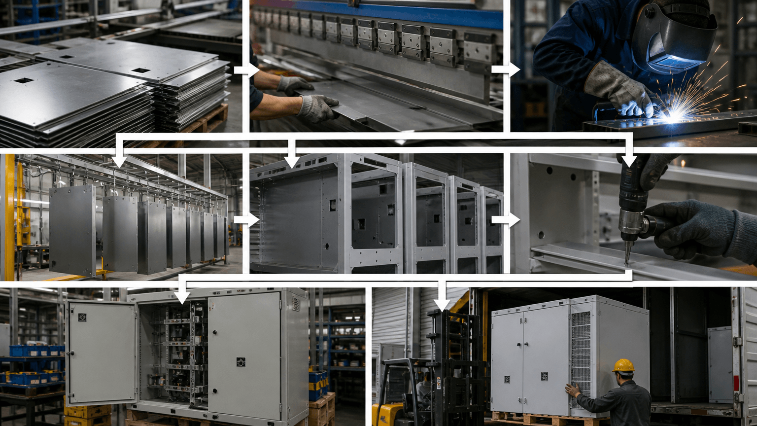
A route may start with laser cutting or CNC punching, continue through bending and a check of critical holes and datums, then branch into welding or mechanical fastening. Surface preparation, finishing, hardware installation, and complete mechanical verification follow the selected route. A knock-down product and a finished cabinet therefore need different handoff points.
Choose the Right Fabrication Assembly Delivery State
| Delivery state | Illustrative example | Factory output | What shifts downstream |
|---|---|---|---|
| Loose fabricated parts | Knock-down display rack, flat-packed bracket set, or replacement panels | Cut, bent, and, where specified, finished parts with specified loose fasteners | The customer handles more joining and alignment. Packaging stays compact, and individual parts remain easier to replace. |
| Welded subassemblies | Equipment frame, support base, or enclosure shell | Members are fixtured and permanently welded in the agreed pre-finish or finished condition | The factory establishes frame relationships earlier. The fixed unit may need more transit protection and offers less disassembly. |
| Finished mechanical assembly | Cabinet with door, latch, panels, feet, and specified hardware | Finished structure with mechanical components installed and assembly fit checked | Customer-side labor falls, but finish protection, service access, replacement paths, and final packaging need attention. |
| Integration-ready unit | Enclosure prepared for customer electronics or a proprietary module | Agreed openings, mounting patterns, clearances, rails, and mechanical hardware | Mechanical preparation ends at the agreed interface. Electrical or proprietary integration remains separately defined. |
No single delivery state suits every product. A long display rack may suit knock-down shipment. A welded equipment frame may need factory-established squareness. A serviceable cabinet may need removable panels even when the supplier ships a finished assembly. Product architecture and downstream operations should drive the choice.
Why Assembly Fit Depends on Part Relationships
Individual parts can meet their own drawings while the completed unit still fails to fit. Mating-hole position, bend location, frame squareness, finish condition, and hardware engagement describe relationships. Assembly verification must therefore examine the assembled condition, not only isolated dimensions.
Formed geometry moves mating features
Flat patterns depend on bend deductions, K-factor assumptions, bend radius, tooling, material behavior, and springback compensation. Bend variation can move a hole after forming, especially near a flange or bend line.
Two panels may meet their individual drawings while their mating holes, slots, flanges, or door edges miss one another. A shared datum system and assembly-level dimensions connect the flat, formed, and assembled conditions. Identify the hole patterns, edges, openings, and reference surfaces that control the next assembly step.
Weld distortion changes the frame reference
Welding sequence, fixture strategy, joint design, and heat input can affect distortion, flatness, and frame squareness. A shell can shift enough to affect door movement. A bracket can move enough to change a panel gap.
The assembly drawing should define the surfaces and openings that control later installation, not only the lengths of individual members. Yishang’s custom metal frames page provides a relevant product path for frame geometry and downstream assembly considerations.
Finish layers affect close interfaces
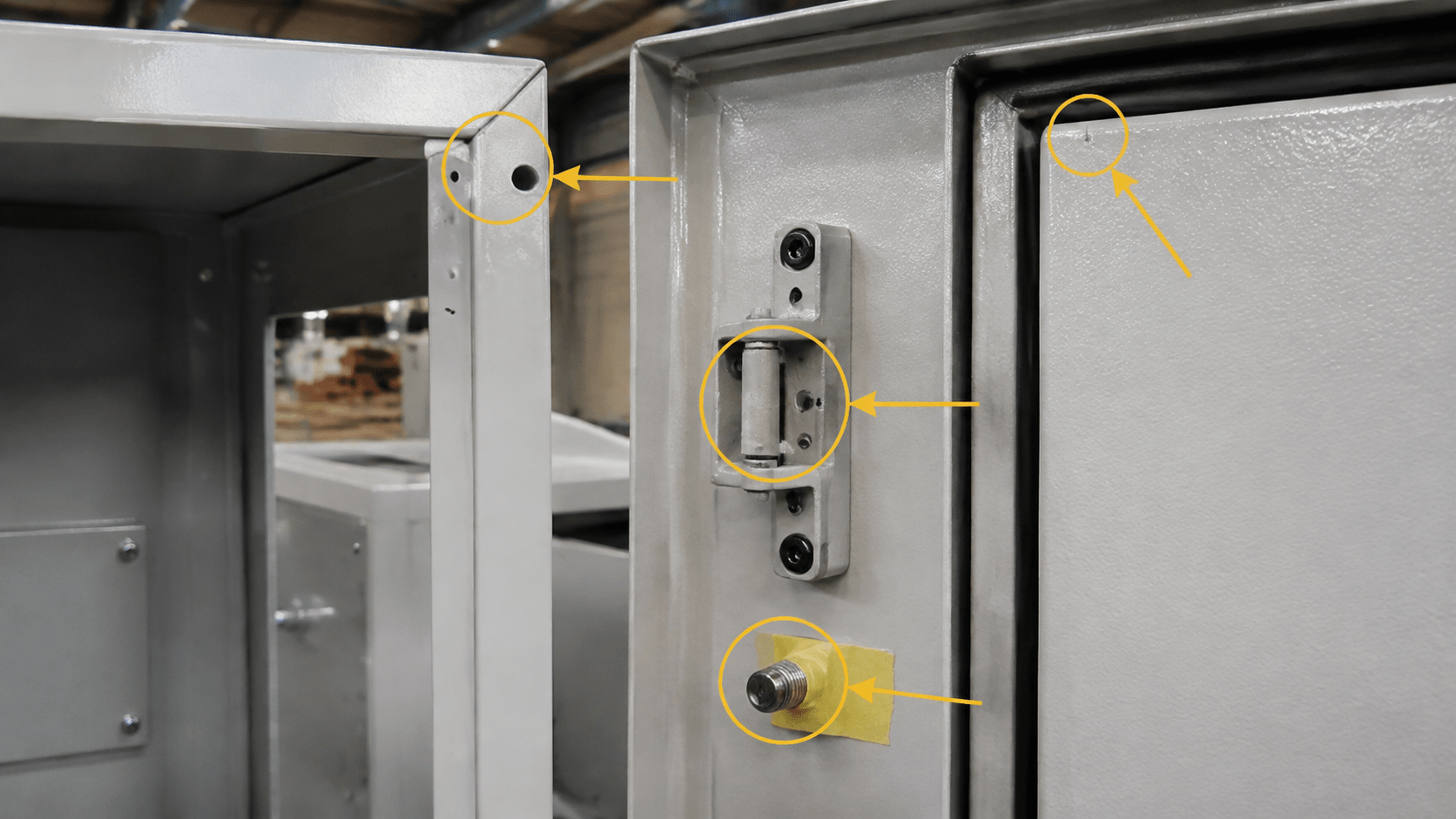
Powder coating, plating, and anodizing change the condition of a mating surface. Coating thickness can affect slots, hinge leaves, latch openings, close-fitting panels, threads, and other interfaces.
Identify grounding contact areas, finish-free weld locations, and protected mating surfaces where the design requires them. Coating over a thread can obstruct installation. Finish trapped in an inaccessible interface can also complicate future service.
Purchased hardware closes the fit chain
Hinges, latches, handles, feet, inserts, and fasteners add their own geometry, orientation, and installation requirements. A hinge can meet its own specification yet fail to align with the door and its mating feature.
The BOM and assembly drawing should identify the intended hardware and its relationship to panels, brackets, and frames. A machined insert or purchased latch also needs clear interface dimensions. Installing it into sheet metal does not make machining part of sheet metal fabrication.
Sequence Permanent Joints, Finishes, and Service Hardware
Sequence matters because permanent joints, surface finishes, and removable hardware have different access and protection needs. A welded shell may need dimensional control before coating. Hinges, latches, and removable panels may need installation afterward.
- Define the interfaces. Mark welded joints, weld-in features, removable fasteners, purchased hardware, finish-sensitive areas, and customer-installed interfaces in the product documents.
- Cut and form the parts. Produce panels, brackets, doors, and frame members. Review critical holes, datums, and mating features before irreversible joining or finishing.
- Complete permanent joining. Weld the structural shell or frame with the specified fixture approach. Grind or polish only where the design or finish requires it.
- Apply the finish. Teams commonly apply final coating after permanent welded work and surface preparation. Protect threads, grounding points, close fits, and contact areas through masking or another agreed method.
- Install removable hardware. Install hinges, latches, handles, feet, panels, and screws after finishing when that protects the coating and preserves service access.
- Complete the mechanical assembly. Confirm final relationships and prepare only the agreed openings, mounting features, and clearances for customer-side integration.
Design requirements can change this sequence. Install weld nuts, studs, and other permanent features before coating when the product requires them. Install removable threaded hardware afterward when that protects the finish. Some inserts or captive components need a different order. The design, finish system, accessibility, and masked-area requirements should control the decision.
Verify the Unit, Not Just the Parts
A cabinet can meet individual part dimensions and still arrive with a binding door, a latch that misses its strike, or a mounting pattern that does not match the next component. Verify the product at the same assembly state that the customer or downstream operation will receive.
- Establish the baseline. Use the current part drawings, assembly drawing, BOM, work instructions, and identified critical characteristics. An approved prototype or first article can provide the reference condition where specified.
- Check components before assembly. Confirm revision, material, key dimensions, hole and slot locations, bends, threads, finish condition, and specified hardware.
- Verify subassemblies. Check welded frame squareness, relevant flatness, bracket orientation, mounting-hole relationships, and panel or door fit. Assembly fixtures can help reproduce the intended datum relationships.
- Check the complete mechanical unit. Review assembly-level dimensions, panel gaps, door movement, hinge and latch alignment, fastener presence and orientation, and specified torque where applicable. Look for interference, coating damage, trapped surfaces, and inaccessible service points.
- Record the agreed evidence. Use controlled work instructions, inspection records, prototype approvals, and batch traceability when the project requires them.
Individual inspection asks whether a part conforms on its own. Assembly verification asks whether the parts fit together in the required relationships. See Quality Control for related context. These checks address the mechanical assembly only. Electrical wiring, electronics installation, commissioning, environmental or ingress protection testing, pressure testing, load testing, and other functional tests require separate requirements, equipment, and responsibilities.
Frequently Asked Questions
What hole alignment details should buyers define before requesting a quote?
Buyers should define the functional requirement, drawing notes, critical dimensions, material or process expectations, and any inspection points related to hole alignment. This helps suppliers quote the same manufacturing scope instead of making different assumptions.
How can tolerance stack affect cost, fit, or lead time?
tolerance stack can change tooling, forming, welding, finishing, inspection, or rework requirements. If buyers do not clarify it early, two supplier quotes may look comparable while covering different production risks.
Why should mating parts be reviewed before prototype approval?
mating parts may look acceptable on a single sample but become harder to control during batch production. Buyers should confirm whether the prototype reflects the same process, finish, and inspection conditions expected for production.
What inspection points matter most for fabrication assembly projects?
Important inspection points usually include fit-critical dimensions, holes or mating areas, cosmetic surfaces, finish build-up, welded or formed features, and any dimensions that affect downstream assembly. These points should appear in the RFQ or drawing notes.
How can buyers reduce fit-up inspection risk before batch production?
Buyers can reduce risk by clarifying drawings, locking key material and finish assumptions, defining inspection timing, approving a representative sample, and confirming which dimensions or surfaces require tighter process control.
How can Yishang help review fabrication assembly requirements?
Yishang can review drawings, RFQ notes, material requirements, tolerance expectations, finish details, samples, and assembly needs to identify unclear assumptions before quoting or batch production.