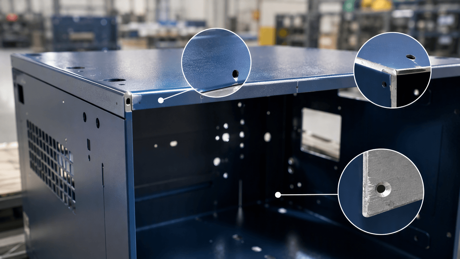
Quick answer: Powder coating process steps for OEM sheet-metal parts run from part preparation and cleaning through substrate-specific pretreatment, masking and fixturing, electrostatic powder application, controlled heat curing, cooling, and inspection. Metal powder coated describes a fabricated metal substrate with a dry powder film: the applicator charges and deposits the powder, then heat melts and cures it into a coating.
For example, an enclosure can move through laser cutting, CNC punching, bending, welding, coating, inspection, and final assembly. Fabrication creates the enclosure geometry; powder coating finishes the prepared metal. It does not replace cutting, machining, bending, welding, or assembly.
What metal powder coated means for an OEM part
Powder coating is a surface-finishing process, not a metal material or a separate fabrication method. The substrate supplies the part’s structure and dimensions, while the cured film changes its appearance and may influence corrosion behavior, clearances, and handling. Steel, aluminum, stainless steel, galvanized steel, and other substrates can require different preparation and coating-system validation.
This distinction matters when a drawing combines sheet-metal panels with machined inserts, fasteners, or welded features. Fabrication establishes the part geometry; machining establishes features on a machined component; the finisher coats the specified surfaces; and inspection confirms appearance and function. The related fabrication route is described in Custom Sheet Metal Fabrication Built to Your Drawings.
Powder coating process steps, from fabrication to inspection
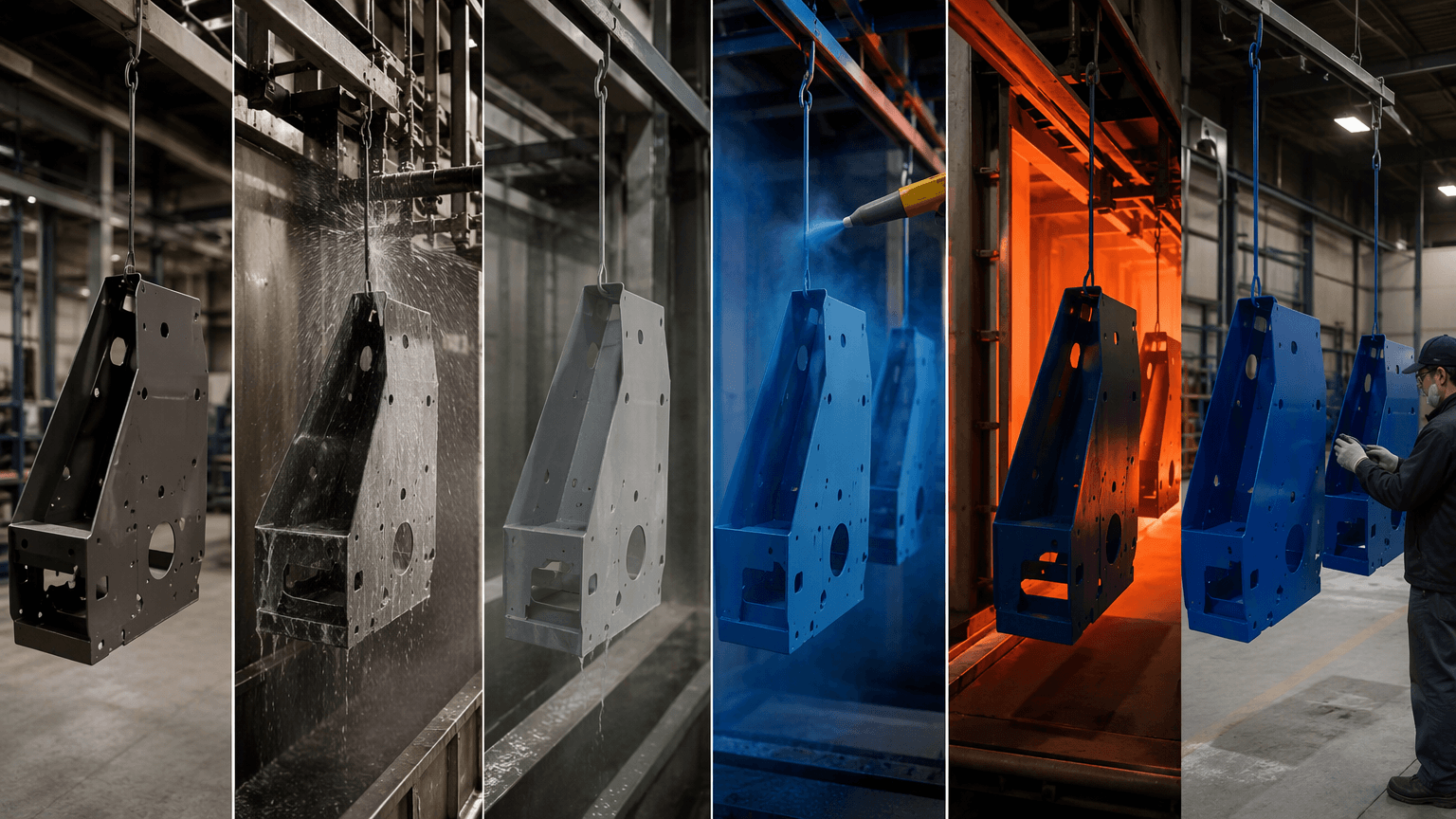
The exact route depends on the substrate, fabricated condition, geometry, selected powder system, exposure, and assembly plan. A typical OEM process flow is:
- Review and prepare the fabricated part. Address burrs, loose scale, weld spatter, dirt, and residues. Confirm that operators can clean and coat holes, threads, vents, recesses, and handling points as intended.
- Clean and degrease. Remove oils, cutting fluids, fingerprints, and other contamination that could affect adhesion or appearance. Choose the cleaning and rinsing route to suit the substrate and following treatment.
- Select compatible pretreatment. Remove rust or oxides with abrasive preparation or another suitable method. Follow degreasing with phosphating, a conversion treatment, or another substrate-specific route selected for the alloy and exposure conditions.
- Mask, fixture, and establish grounding. Use plugs, caps, tape, fixtures, or other methods to protect threads, grounding zones, mating faces, and other no-coat areas. Provide stable support and suitable grounding for the part.
- Apply the powder. Electrostatic charging helps dry particles adhere to the prepared surface before heating. Orientation, edges, welds, internal corners, and deep recesses affect deposition and coverage.
- Cure the coating. Heat causes the powder to flow, form a film, and develop its cured condition. This controlled melt-and-cure step differs from simple drying. Let the powder manufacturer’s cure basis and actual part-temperature requirements govern the settings.
- Cool, inspect, and release. Let the part cool enough for safe handling, then check appearance, coverage, masking, specified coating build, handling damage, and functional fit before packaging or the agreed assembly operation.
Process boundary: Powder coating finishes a prepared surface within the manufacturing sequence. It does not replace laser cutting, CNC punching, bending, welding, CNC machining, or mechanical assembly.
What the drawing must define for production
A note that says only powder coated leaves preparation, appearance, masking, acceptance, and assembly decisions open. The finish schedule or purchase order should give production and inspection a common basis.
| Specification item | What to define |
|---|---|
| Part identity and substrate | Part number, metal grade or alloy, thickness, fabricated condition, welded features, and whether the part arrives loose or assembled. |
| Surface preparation | Define cleaning, abrasive preparation, conversion treatment, and substrate-specific compatibility requirements. |
| Appearance | Color reference or physical sample, gloss, texture, visible surfaces, and acceptable variation. |
| Powder system and cure | Name the selected coating system, exposure requirements, and cure basis for that system. Avoid generic settings. |
| Film build | Add a target film-thickness range only if the project or coating supplier defines it, along with the measurement method and locations. |
| Masking and no-coat areas | Threads, holes, grounding pads, labels, electrical contacts, bearing or sliding areas, datum surfaces, and mating faces. |
| Coverage | Set expectations for edges, welds, recesses, channels, internal faces, corners, and planned hanging or contact marks. |
| Inspection and approval | Set viewing conditions, appearance, coverage, adhesion, film build, masking, assembly fit, sampling, acceptance variation, and rework or touch-up disposition. |
| Environment and handling | State expected exposure, moisture or chemical contact, assembly order, protection, and packaging constraints. |
If the route remains under evaluation, review the available Surface Finishing options against the required appearance and functional conditions.
Design review: protect coating-critical interfaces
Before releasing a drawing, review every feature that must remain dimensionally, electrically, or mechanically functional after coating. A flat panel may look acceptable while its threads, grounding pad, seal, or close-fit flange creates an assembly problem.
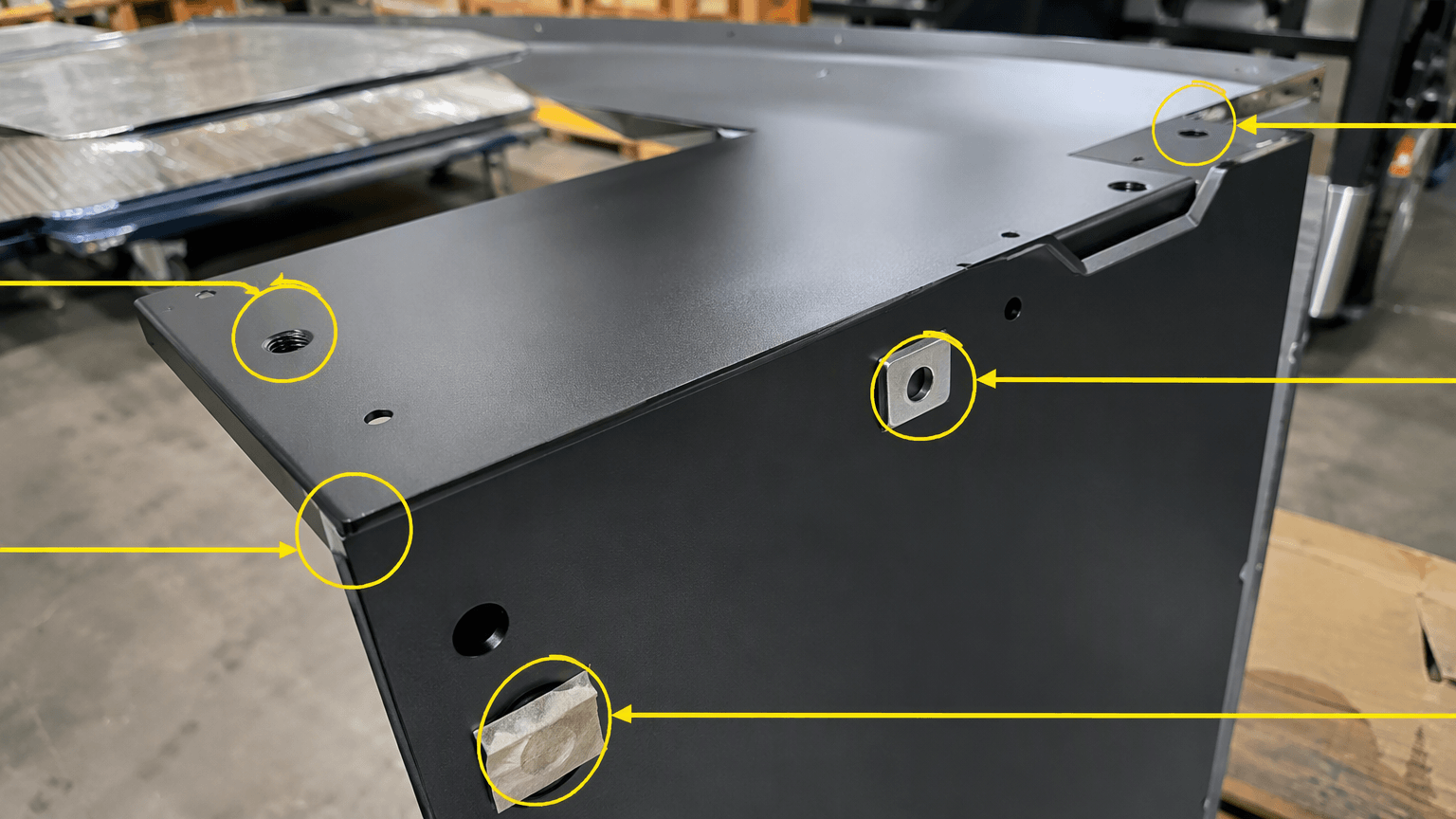
- Threads, holes, and close fits: Coating build can reduce clearance or interfere with fastener installation. Define plugs, caps, masks, allowances, or an approved post-coating operation.
- Grounding and electrical contact: Protect ground pads, bonding faces, and contact zones with masking or a defined coating-removal step. Do not assume a sprayed surface will remain electrically functional.
- Mating and sliding faces: Flanges, press-fit areas, bearing seats, slots, seals, and latch interfaces need explicit finish limits and an assembly check.
- Edges and recessed geometry: Sharp edges, narrow channels, deep recesses, internal corners, and Faraday-cage-like features can create coverage or build variation. Review edge preparation and visible-surface acceptance.
- Welded and enclosed sections: Spatter, porous welds, trapped oil, moisture, or contamination may contribute to bubbling, pinholes, or poor appearance. Hollow sections may need suitable drain, vent, handling, and cleaning access.
- Machined components: A turned or milled insert, shaft, or bracket remains a separate machined component even when installed in a sheet-metal assembly. Define whether the finisher coats it, masks it, leaves it bare, or installs it after coating.
Review the coating sequence against hinges, fasteners, seals, panels, grounding straps, and final fastener installation. Protect functional interfaces through drawing requirements rather than supplier assumption.
Approval and defect investigation
Approve a prototype or first article against an agreed color reference or physical sample, gloss, texture, visible-surface definition, lighting, viewing condition, and acceptable variation. Lighting, viewing angle, texture, batch, substrate, film build, and part geometry can change the comparison.
Use agreed methods for appearance, coverage, masking, adhesion, film build where specified, and assembly fit. The project specification controls acceptance; no universal pass-or-fail condition applies to every powder-coated part.
A practical investigation separates visual variation from a process or functional failure:
- Record the defect location, affected surface, batch, part orientation, and cosmetic or functional impact.
- Compare the part with the sample and drawing requirements under the agreed viewing conditions.
- Review the powder reference, substrate, cleaning and pretreatment route, masking, hanging, and cure records.
- Examine the relevant feature, such as a recess, edge, weld, threaded hole, or mating face.
- Document disposition, rework, touch-up, replacement, and any process change needed for repeat production.
| Observed issue | Investigation direction |
|---|---|
| Color, gloss, or texture variation | Check the reference, lighting, viewing angle, batch, substrate, film build, cure history, and geometry. |
| Peeling or poor adhesion | Review contamination removal, rust or oxide preparation, conversion treatment, substrate compatibility, and cure. |
| Bubbling or pinholes | Investigate contamination, trapped moisture, porous welds, outgassing, substrate condition, and excessive build. |
| Corrosion at edges or welds | Check edge preparation, coverage, weld cleaning, pretreatment, handling damage, and the specified environment. |
| Assembly interference | Verify masking, coating build, holes, threads, mating faces, fastener installation, and post-finish fit inspection. |
When repeatability matters, retain the sample and document the powder reference, pretreatment route, cure records, batch information, and inspection findings. Coordinate the inspection plan with Quality Control requirements.
Select the finish against the complete part
Finish selection depends on substrate, geometry, part size, environment, appearance, electrical-contact needs, repair method, batch grouping, and process constraints. Powder coating is not interchangeable with liquid paint, plating, anodizing, or galvanizing.
| Route | It may fit when | Verify before selection |
|---|---|---|
| Powder coating | A heat-compatible fabricated or welded part needs a dry-film finish and the buyer can group parts for processing. | Substrate pretreatment, exposure, oven and hanging limits, recess coverage, masking, repair, and assembly fit. |
| Liquid paint | A large or heat-sensitive part, field repair, or specialized wet-paint appearance matters. | Preparation, solvent handling, drying or curing, overspray, touch-up, and batch scheduling. |
| Anodizing | An aluminum component needs an electrochemical oxide treatment and the alloy and geometry are suitable. | Alloy response, appearance range, dimensional effects, contact areas, geometry, and bath-size limits. |
| Plating | The project needs a deposited metallic surface, electrical contact characteristic, wear-related property, or localized treatment. | Substrate compatibility, current distribution, internal coverage, rack marks, dimensional build, and repair approach. |
| Galvanizing | A steel part needs a metallic zinc protection route for the defined exposure. | Part size, drainage and venting, geometry, appearance, handling, and whether a compatible topcoat is needed. |
| Bare, polished, or brushed stainless steel | The natural stainless-steel appearance and absence of coating build-up have priority. | Surface uniformity, handling damage, environmental exposure, cleaning, and electrical or mating requirements. |
Pretreatment complexity, part size, handling, oven or hanging limitations, fixtures, masking, color changes, batch grouping, inspection, rework, and packaging drive cost. Sample approval, substrate preparation, complex masking, batch scheduling, oven constraints, and the required assembly sequence can extend lead time.
For an enclosure or cabinet, review internal surfaces, doors, hinges, fasteners, grounding points, and mating panels as well as the visible exterior. See Custom Sheet Metal Enclosures That Arrive Ready to Assemble for a relevant application context.
For a project-specific finish review or qualified RFQ: send a 2D drawing, 3D model, or clear photographs; substrate grade, thickness, and fabricated condition; part dimensions; welded, enclosed, or recessed features; and prototype or expected production quantity. Include the color reference or sample, gloss, texture, visible-surface requirements, masking and grounding details, thread and mating requirements, target environment, assembly scope, inspection needs, and packaging constraints. Yishang can review the complete custom sheet-metal part and identify pretreatment, masking, fit, and inspection questions for OEM or ODM prototype and batch-production requirements.
Frequently asked questions
These questions often determine whether a powder-coated metal finish brief is complete for an RFQ, prototype review, or drawing release.
What does metal powder coated mean, and is it the same as painted metal?
It means the process applies electrostatically charged dry powder to a metal substrate and then heats the powder until it melts and cures into a coating film. It is painted metal in the broad sense, but the material delivery and heat-curing route differ from liquid paint.
Can aluminum, stainless steel, or galvanized steel be powder coated?
They may suit the process, but compatibility is not automatic. Choose a compatible cleaning and pretreatment route for each substrate and validate the selected powder system for the intended environment, appearance, and assembly requirements.
How are threaded holes, grounding points, and mating surfaces protected?
Identify them on the drawing and protect them with masking, plugs, caps, fixtures, stripping, or an approved post-coating operation. Specify the required bare area and assembly clearance rather than leaving them to assumption.
Why can a production batch differ from an approved powder-coated sample?
Lighting, viewing angle, texture, substrate, film build, cure history, powder batch, and part geometry can affect the comparison. Use a reference and defined viewing and acceptance conditions for samples and production parts.
What commonly causes powder coating to peel, bubble, develop pinholes, or corrode at edges?
Possible causes include contamination, inadequate pretreatment, incompatible substrate preparation, cure deviation, outgassing, poor coverage, sharp edges, handling damage, or excessive coating build. Compare the defect with process and inspection records.