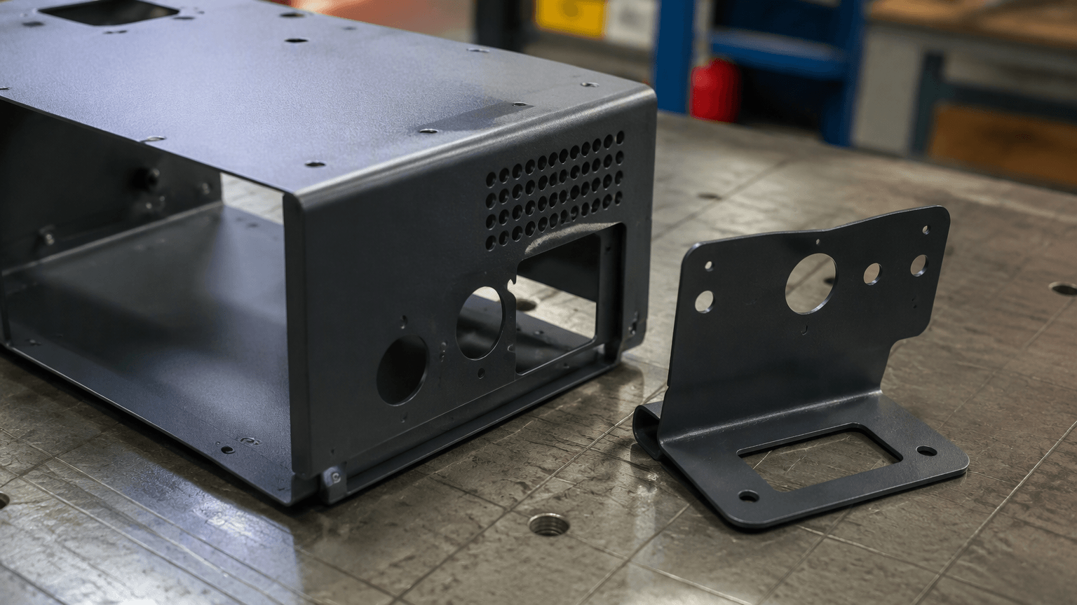
Direct answer: To melt metal together usually means joining metal components through welding or another heat-based joining process. Powder coating does not join metal parts and does not melt the base metal. It is a surface finish applied to an already fabricated part: dry powder is typically applied electrostatically, then heated so the particles flow, melt, and cure into a continuous film.
For an OEM buyer specifying a welded enclosure, bent bracket, or frame, the distinction controls the process route. Cutting, punching, bending, machining, and welding must be completed before the relevant coating preparation, while threads, holes, mating faces, grounding points, appearance zones, and finished dimensions need their own requirements.
On a drawing or purchase order, metal powder coated describes the finished surface—not the material grade, joining method, or complete manufacturing process. Specify those items separately, along with preparation, coating boundaries, inspection, and packaging.
Melt metal together and powder coating are different operations
A common project error is treating “welded and powder coated” as one operation. The welding route can affect distortion, spatter, burrs, and surface condition; the later coating route can affect interfaces, appearance, and clearances. Separating the two helps the supplier quote and inspect the part against the right requirements.
Welding creates a joint between metal components. Depending on the process, the base metal, filler metal, or both may contribute to that joint. Brazing and soldering also use heat to join components, but they rely on a filler material rather than the same type of base-metal fusion as welding.
Powder coating has a different purpose. Heat makes the coating flow and cure while the steel, aluminum, or other substrate remains solid. It produces a finished surface, not a structural joint.
- Cutting and punching create the blank and openings.
- Bending forms the sheet metal geometry.
- Machining creates features through operations such as milling or turning.
- Welding joins components and may require distortion and weld-condition review.
- Assembly installs hardware or combines components in a defined sequence.
- Powder coating finishes the prepared surface after relevant fabrication and joining work.
If a machined insert belongs in a sheet metal assembly, define how it is attached, whether it is installed before or after coating, and which contact or mating areas must remain clear. The complete custom sheet metal fabrication route should coordinate these process boundaries.
From fabricated part to cured finish
On a bracket or enclosure arriving from cutting, forming, and welding, the final appearance depends on preparation as much as on the powder itself. There is no universal route: substrate, surface condition, weld condition, geometry, service environment, and selected powder system determine the appropriate preparation and cure sequence.
A typical route includes:
- Inspect the unfinished part. Check dimensions, welds, burrs, edges, holes, inserts, drainage or venting, and identified cosmetic surfaces. Coating should not hide fabrication defects or correct an out-of-tolerance feature.
- Clean and degrease. Remove oil, dust, fingerprints, shop residue, and other contaminants using a substrate-compatible method.
- Remove rust, scale, or residue. Rust, mill scale, weld residue, and oxidation may require chemical or mechanical removal. Abrasive preparation should suit the material and required surface profile.
- Apply suitable pretreatment. Use a substrate-appropriate conversion treatment or preparation route. Mild steel, galvanized steel, aluminum, and stainless steel should not automatically receive the same treatment.
- Dry, mask, and rack. Address moisture, mask defined interfaces, and select hanging points and orientation for access, coverage, and acceptable rack marks.
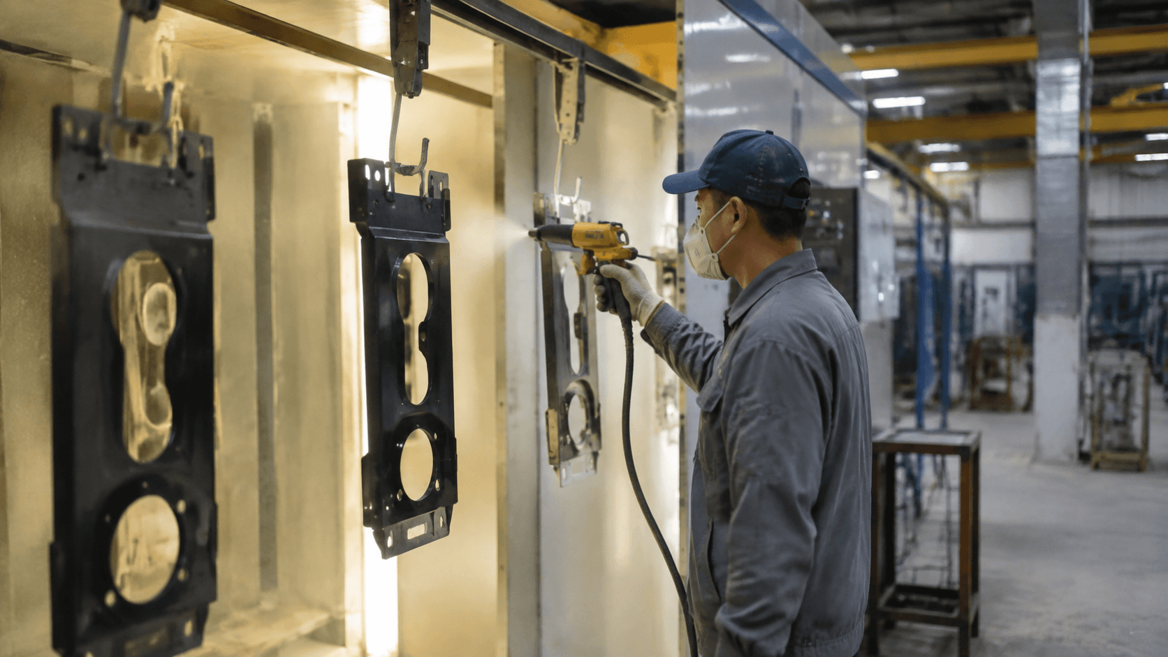
- Apply the powder. Charged powder is sprayed toward the grounded component. Recesses, enclosed corners, edges, and complex welds may make uniform deposition more difficult.
- Heat to the selected system’s cure requirement. The powder flows and cures during the heating cycle. The requirement should follow the powder technical data and the temperature reached by the part, not an unexplained oven-air setting alone.
- Cool and inspect. After cooling sufficiently for handling, check appearance, coverage, thickness, damage, and functional fit.
Contamination, incomplete preparation, poor edge coverage, or an unsuitable cure condition can contribute to adhesion loss, blistering, peeling, corrosion at inadequately protected areas, or inconsistent appearance. These controls should be defined rather than left entirely as supplier assumptions.
Should this metal part be powder coated? A decision matrix
Before releasing an RFQ for a painted bracket or enclosure, review the substrate, exposure, geometry, equipment route, quantity, and appearance together. A finish suitable for one part may not suit a mixed-material assembly, a large component, or a part exposed to chemicals and outdoor handling.
| Decision factor | Questions to resolve | Specification consequence |
|---|---|---|
| Substrate | Is it mild steel, galvanized steel, aluminum, stainless steel, or mixed material? What is the surface condition? | Select compatible cleaning, preparation, pretreatment, and powder. |
| Environment | Will it see moisture, outdoor UV, chemicals, cleaning agents, frequent handling, or unusual temperatures? | Define exposure so the coating system can be selected. Do not assume universal corrosion, weather, or chemical resistance. |
| Size and oven route | Can the complete part be handled, racked, and heated in the available equipment? | Confirm size, handling, and curing constraints before finalizing the design. |
| Geometry | Are there recesses, cavities, sharp edges, complex welds, drainage traps, or restricted spray access? | Review edge preparation, venting, orientation, coverage, and inspectable locations. |
| Interfaces | Which threads, holes, fits, seals, hinges, inserts, and electrical contacts could be affected by coating build? | Define masking, coating limits, post-coating dimensions, and functional checks. |
| Appearance | Which surfaces are visible? Are color, gloss, texture, or component-to-component consistency important? | Identify cosmetic zones and approve a reference or physical sample under agreed conditions. |
| Batch profile | What prototype and production quantities are expected? Will later batches need to match an earlier finish or include color changes? | Plan first-article approval, retained references, and lot-to-lot appearance controls. |
| Alternative route | Does the application need lower-temperature or field application, an aluminum electrochemical finish, a deposited material, or a zinc-coating route? | Compare performance and process boundaries through the broader surface-finishing options. |
Liquid spray painting applies a liquid coating and may be considered when low-temperature processing, field application, or another application-specific property matters. Anodizing is an electrochemical aluminum process; electroplating deposits another material; galvanizing uses a zinc-coating route. These finishes are not interchangeable, and no single route is best for every part.
Drawing boundaries for coating and assembly interfaces
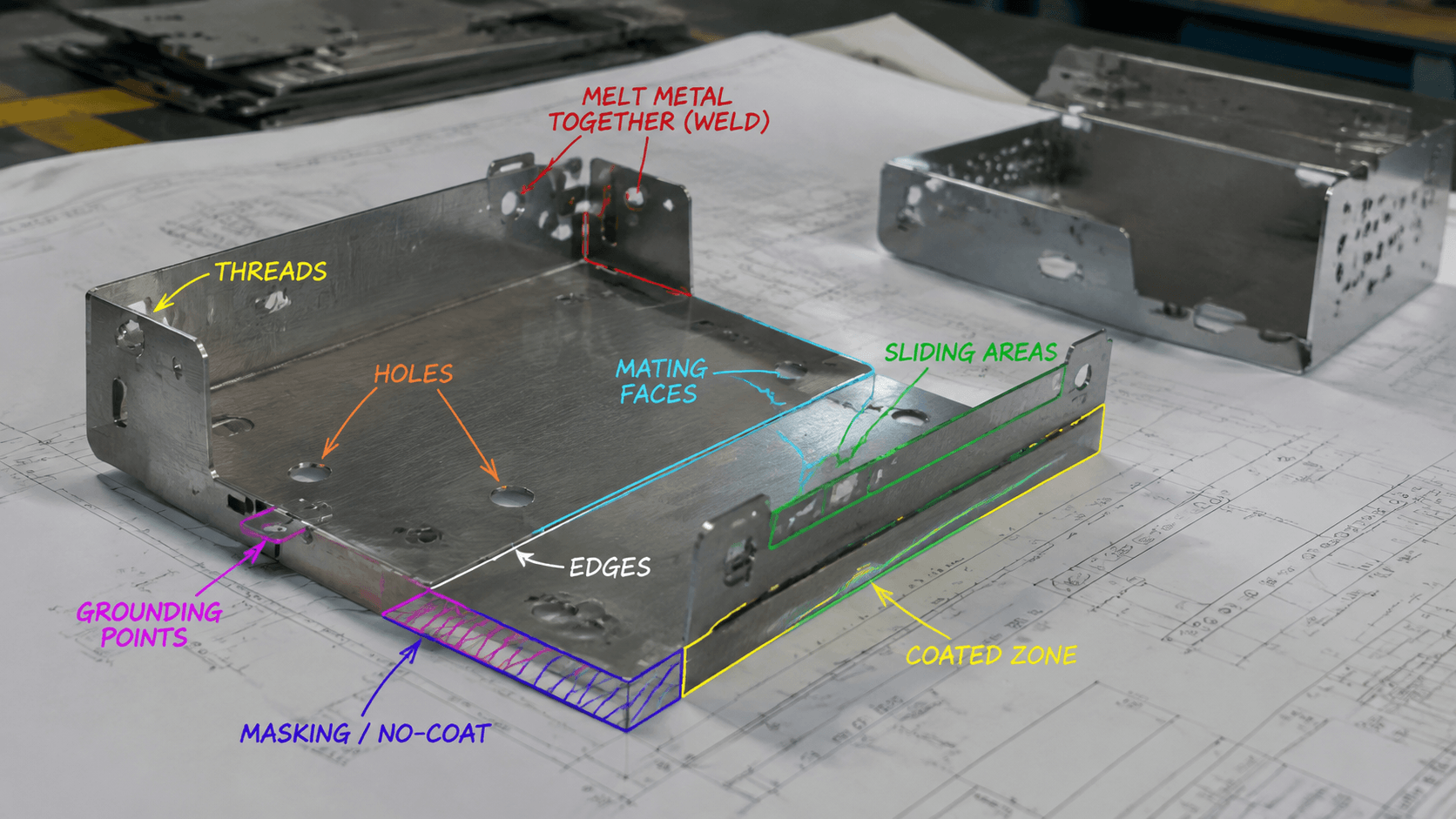
An enclosure may pass a visual review yet fail assembly if coating enters a thread, reduces a clearance, or covers a grounding point. Show coated zones and no-coat zones on the drawing or a finish overlay instead of leaving the supplier to interpret “mask where necessary.”
- Threads: identify internal and external threads that must remain clear, and state whether post-coating cleaning is permitted.
- Holes and seats: define limits for dowel holes, bearing or seal seats, locating features, and finished-size holes.
- Mating and sliding surfaces: mark faces, rails, guides, and fits where coating build could affect alignment, clearance, or movement.
- Hinges, latches, and inserts: state whether each is coated, masked, installed after coating, or protected during handling.
- Grounding and electrical contacts: identify the conductive area because coating can interrupt continuity, and specify the required continuity check when applicable.
- Welds, edges, and cavities: define weld cleanup, spatter and burr removal, edge treatment, drainage, venting, and coverage expectations where they affect preparation or inspection.
Separate cosmetic surfaces from functional interfaces. On a custom sheet metal enclosure, exterior panels may have tighter appearance requirements than hidden mounting surfaces, but gasket interfaces, grounding studs, door hardware, and assembly holes still need explicit treatment.
Building an executable powder-coating specification
“Powder coat black” is not enough to quote or accept a repeat-production OEM part reliably. The drawing, purchase order, or RFQ should identify the material, selected or proposed coating route, visible surfaces, interfaces, cure basis, and inspection evidence without requiring guesswork.
| Category | Information to provide |
|---|---|
| Material and condition | Base-metal type, grade where applicable, thickness, welded condition, and known oil, rust, scale, or contamination. |
| Preparation | Required route if established, or a request for a substrate-appropriate recommendation for approval. |
| Powder system | Selected system when known, or service environment and performance needs to guide selection. |
| Appearance | Color identifier or approved physical sample, gloss level or range, texture, cosmetic zones, and acceptable variation. |
| Film and coverage | Target film thickness and tolerance based on the selected system, measurement locations, edge and recess expectations, and rack-point treatment. |
| Boundaries | Coated, uncoated, masked, threaded, mating, sliding, sealing, and grounding areas; state which dimensions apply after coating. |
| Cure basis | A requirement tied to the powder system and actual part condition, rather than oven-air temperature alone. |
| Inspection | Appearance, color, gloss, texture, thickness, adhesion or cure when required, dimensions, fit, threads, holes, and electrical contacts. |
| Packaging | Protection against scratching, chipping, rubbing, pressure marks, and contact damage during storage and shipment. |
An inspection sequence for appearance, fit, and repeatability
For a prototype or initial batch, approval should connect the finish to the drawing revision, critical tolerances, functional interfaces, and evidence required with later shipments—not just to the color of one sample.
- Confirm the basis. Verify the drawing revision, finish note, approved sample, cosmetic zones, lot identification, and agreed lighting and viewing conditions.
- Review appearance and coverage. Check for bare areas, contamination, pinholes, blisters, chips, scratches, inconsistent texture, and unacceptable edge or recess coverage.
- Compare color, gloss, and texture. Use the approved reference under consistent conditions and judge visible and hidden surfaces against their defined requirements.
- Measure film thickness. Use a suitable instrument at agreed locations. Substrate, curvature, edges, and geometry can affect readings, so locations belong in the specification.
- Run adhesion, cure, or performance checks when required. Define the agreed method, acceptance basis, sampling, and whether the check uses a part, test piece, or representative coupon.
- Verify fit and function. Check thread engagement, hole size where required after coating, mating fit, moving hardware, seals, inserts, and grounding or electrical contact points.
- Review records and packaging. Separate shipment evidence from retained process records, and check protective packaging before release.
Initial-part or initial-batch approval establishes the reference for later lots. Subsequent checks can then focus on color, gloss, texture, coating boundaries, fit, and handling damage. Related dimensional and finish controls can be coordinated through the documented quality control route.
Frequently asked questions
These questions come up when a finish reference must become a usable drawing note or RFQ requirement.
What does “metal powder coated” mean on an OEM drawing?
It means a fabricated metal part receives a dry powder finish that is typically electrostatically applied and heat-cured. It does not define the metal grade, welding method, tolerances, or complete route.
Is powder-coated metal the same as metal painted with liquid paint?
No. Powder coating uses dry material and typically heat to form the film; liquid painting uses a liquid material and a different application and cure route.
Can holes, threads, and grounding points remain functional after coating?
Yes, when the drawing defines masking or no-coat limits, post-coating dimensions, permitted thread cleaning, and fit or continuity checks.
Can aluminum, stainless steel, and galvanized steel be powder coated?
They may be candidates, but each requires review of surface condition, pretreatment, powder compatibility, geometry, heating constraints, and service exposure.
How can buyers control appearance across repeat batches?
Define color, gloss, texture, cosmetic zones, viewing conditions, acceptable variation, an approved reference or initial batch, and lot-to-lot inspection controls.