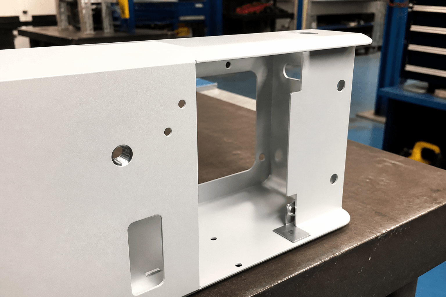
Design for welding means developing a fabricated metal part so joints can be accessed, fitted, welded, cleaned, inspected, and assembled as intended. For a welded enclosure, frame, bracket, or cabinet, powder coating is a downstream finishing consideration: it must support the welded design without obscuring critical interfaces or creating avoidable rework.
Metal powder coated usually means a fabricated metal part whose prepared surface receives dry powder that is electrostatically deposited and heated to melt and cure into a coating film. That phrase identifies a finish, not a complete production requirement. The drawing still needs to define the welded construction, material, finish zones, fit interfaces, and acceptance criteria.
In practical terms: design the welded part first around joint access, fit-up, distortion, material and thickness, weld definition, and inspection. Then specify how preparation, powder coating, masking, dimensional checks, and assembly will be controlled after welding.
Start with the welded design, not the finish label
A powder-coated finish cannot compensate for a joint that is inaccessible, poorly fitted, distorted, or difficult to inspect. Before selecting a finishing route, review the part as a welded assembly and ask whether the fabricator can consistently make the joint and whether the finished assembly can perform its intended function.
- Joint accessibility: Provide a clear path for the welding tool, operator, fixture, and inspection access. A joint hidden behind a flange or inside a narrow enclosure may be difficult to weld consistently or verify.
- Joint configuration: Select lap, butt, corner, or other joint arrangements according to the load path, available access, required appearance, and fabrication sequence. Do not rely on a joint description that leaves the weld location or extent ambiguous.
- Fit-up: Control gaps, alignment, flange relationships, and locating features before welding. Parts that are forced into position can move after release or produce inconsistent weld profiles.
- Material and thickness: State the base-metal grade or family and thickness for each component. Different thicknesses and material combinations can change heat input, distortion risk, preparation needs, and the suitability of a proposed weld route.
- Weld definition: Use drawing symbols, detail views, or plain-language notes to identify weld location, continuity, side, size or other required characteristics, and whether the weld is structural, sealing, cosmetic, or limited to an intermittent location. The note should be clear enough that the supplier does not have to infer the requirement.
- Distortion control: Consider the order of forming, fixturing, tack welding, and final welding. Long seams, thin sections, unequal restraint, and concentrated heat can affect flatness, squareness, hole position, and mating interfaces.
- Cleanup and inspection: Define where spatter removal, weld blending, edge treatment, or visible-surface cleanup is required. Identify welds and dimensions that must be inspected before finishing and interfaces that must be checked again after coating.
These decisions are part of design for welding. Powder coating follows them as a surface-finish route, although some parts or subassemblies may be intentionally finished before final assembly. The actual sequence should be agreed for the part, hardware, and assembly method rather than assumed to be universal.
Design the fabrication route around access and distortion
Laser cutting, CNC punching, bending, machining, and welding can create the components and joints, but the order of operations affects the finished result. A supplier feasibility review should examine the 2D drawing and 3D model together, especially where a welded assembly contains tight interfaces or enclosed areas.
| Design condition | Why it matters during welding | Useful drawing or process control |
|---|---|---|
| Restricted tool or operator access | The joint may be difficult to reach, position, tack, or inspect without an alternative orientation or sequence. | Show access requirements in a section or detail view and review fixture and inspection access before release. |
| Thin or mixed-thickness components | Heat can affect distortion, burn-through risk, fit-up, or the appearance of the joint. | Identify material and thickness for every welded component and review the joint design with the fabrication route. |
| Long seams and large panels | Welding can change flatness, squareness, hole position, or the relationship between mating faces. | Identify critical datums and interfaces, then plan fixturing, tack locations, weld sequence, and post-weld checks. |
| Close-tolerance holes and mating features | Heat movement or weld distortion can affect fastener alignment, insertion, closure, or assembly. | Mark fit-critical features and check them after welding and again after coating where the finish can affect clearance. |
| Visible welds and cosmetic faces | Spatter, undercut, uneven profiles, grinding marks, and discoloration may remain visible beneath the finish. | Separate structural requirements from cosmetic requirements and define the required cleanup on visible surfaces. |
| Enclosed cavities | Internal joints may be difficult to weld, clean, inspect, coat, or drain. Trapped residues can also affect preparation. | Review tool access, inspection access, openings, venting, drainage, and the required internal coverage before production. |
| Welded-on hardware or inserts | Hardware can obstruct access, become distorted, or create a different finish and masking requirement. | State whether the item is welded, installed before coating, masked, or installed after coating, and check the resulting interface. |
Designing for welding does not mean adding welds everywhere. It means locating and defining joints that can be made repeatably while preserving the part’s dimensions, access, appearance, and downstream assembly requirements. See Custom Sheet Metal Fabrication Built to Your Drawings for the upstream fabrication context.
What metal powder coated means after welding
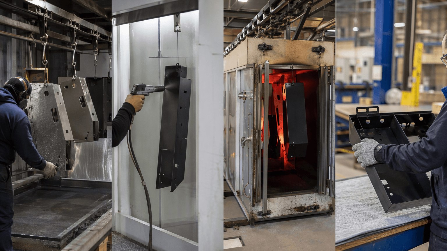
When this phrase appears in a supplier listing or purchase request, it is normally shorthand for powder-coated metal. The part is typically fabricated and welded first, its surface is prepared, and dry polymer powder is electrostatically applied before controlled heating forms the final coating film. However, a component or subassembly can be coated before final assembly when the design and masking plan call for that route.
The coating is attracted to a grounded, prepared part. Heating then melts and cures the selected powder system according to its requirements and the part’s actual thermal profile. The exact preparation and cure window depend on the substrate, contamination, geometry, coating system, and required performance; there is no universal recipe.
The phrase does not identify the metal grade, preparation method, appearance, coverage, or finished fit. It describes a surface finish, not a raw material, powder-metallurgy process, or generic painted-metal product.
From welded fabrication to the controlled finish
The practical route normally includes these stages:
- Review the substrate and welded condition. Confirm the metal grade or family, thickness, dimensions, weld condition, previous treatment, and any areas that must remain electrically conductive or dimensionally controlled.
- Complete the applicable fabrication operations. Cutting, forming, machining, and welding are generally completed before coating when the coating would obstruct later work. The planned sequence may differ for parts intentionally finished before final assembly.
- Prepare the surface. Cleaning and degreasing remove oils and residues. Depending on the substrate and requirement, preparation may include rust removal, phosphating, blasting, or another applicable treatment. Weld spatter, oxidation, sharp edges, and residues may require additional attention.
- Mask and fixture. Control threads, grounding points, mating faces, holes, press-fit areas, and other no-coat zones. Plan rack or hanging points so contact marks are understood before coating.
- Apply the powder. Charged powder particles are attracted to the grounded, prepared part. Recesses, internal corners, narrow areas, and enclosed geometries require a coverage review.
- Heat and cure. Heat the part according to the selected powder system and its thermal profile. The coating supplier or finisher should confirm the applicable process window for the actual part.
- Inspect and assemble. Check the agreed appearance, coverage, masked boundaries, dimensions, electrical-contact areas, assembly fit, and any defined coating tests.
Contamination, insufficient preparation, uneven coverage, or an unsuitable cure window can affect adhesion, appearance, and corrosion performance. Powder coating should therefore be treated as a controlled downstream process, not as an automatic result of adding the words powder coat to a drawing. See Surface Finishing for the place of powder coating within the broader finishing route.
Turn the welded design and finish into an executable specification
A drawing or purchase order should connect the welded construction to the finished-condition requirement. Use drawing views, weld details, a zone map, and clear notes to define:
Quote-ready specification checklist
- Welded construction: State the base-metal grade or family, thickness, component relationship, weld locations, weld extent or characteristics, visible-surface requirements, and any critical datums or inspection points.
- Fabricated condition: Identify whether the item is cut, bent, machined, welded, or supplied as a subassembly, and note dimensions or interfaces that must be checked after welding.
- Finish reference: Provide a color reference or approved physical sample. A color name alone is not enough for consistent approval.
- Appearance: Define gloss, texture, visual appearance expectations, and customer-visible surface requirements.
- Coated zones: Identify whether all accessible surfaces or only selected external, internal, front, rear, or other faces are to be coated.
- Masked and controlled zones: Mark threads, holes, grounding points, mating faces, press-fit areas, hinges, latches, and other no-coat or controlled-coat features.
- Boundaries and contact marks: Define permitted overspray, transition boundaries, and acceptable rack or fixture marks, especially on visible faces.
- Inspection and batch control: Specify film thickness, adhesion, curing, corrosion, or other checks only when required, together with the method and acceptance criteria. Include quantity, batch grouping, and sample or first-article approval expectations.
A coordinated callout can state: weld the indicated joints according to the drawing details; powder coat the indicated faces using [color reference], [gloss], and [texture]; mask [specified interfaces]; and accept appearance against [approved sample] using [defined checks]. Complete each bracketed field for the actual part.
Protect fit, electrical contact, and appearance at the coating stage
Coating must be considered at the interfaces that matter after welding. Film build-up or overspray can affect thread engagement, clearance, insertion, closure, movement, alignment, or direct metal-to-metal contact.
| Feature | Potential risk | Drawing or process control |
|---|---|---|
| Welds and seams | Spatter, oil, rust, residue, oxidation, or uneven profiles can affect preparation and appearance. | Define weld-cleanliness and visible-surface requirements, including any cleanup before finishing. |
| Edges and corners | Sharp or poorly prepared edges can contribute to coverage and appearance variation. | Call out the required edge condition where it affects handling, appearance, or function. |
| Threads, holes, and press fits | Film build-up can interfere with thread engagement, clearance, insertion, or gauging. | Show the controlled zone and verify it with the mating fastener, part, or agreed gauge. |
| Grounding points | A coating film can interrupt direct metal-to-metal electrical contact. | Mark the contact pad or masked area and define the required finished contact condition. |
| Mating faces, hinges, and latches | Overspray or build-up may affect closure, movement, alignment, or fastening. | Identify controlled or uncoated faces and include a functional assembly check. |
| Recesses and enclosed areas | Narrow geometry can be harder to prepare, coat, cure, and inspect consistently. | Show required coverage and review access, openings, venting, and drainage where relevant. |
| Rack or hanging points | Fixture contact can leave marks or small uncoated areas. | Locate contact points where possible and state whether marks are acceptable on visible faces. |
Do not let coat all surfaces override detailed no-coat callouts. On a welded cabinet or enclosure, visible faces, internal surfaces, grounding points, threads, and hardware should be reviewed together. See Custom Sheet Metal Enclosures That Arrive Ready to Assemble for a relevant application context.
Compare finishing routes by the part’s function
Powder coating is not interchangeable with liquid paint, plating, anodizing, or galvanizing. Compare the routes against substrate, part size and handling, thermal constraints, coverage needs, electrical contacts, dimensional sensitivity, appearance, operating environment, and production volume.
| Route | Process and substrate context | Design and selection focus |
|---|---|---|
| Powder coating | Dry polymer powder is electrostatically applied and heat-cured on a selected metal substrate. | Check thermal compatibility, part size and handling, recess coverage, masking, fit, contacts, appearance, and batch control. |
| Liquid paint | A wet coating is applied and then dried or cured by a different route. | Consider wet-film access, drying or curing conditions, repair needs, heat exposure, and appearance. |
| Electroplating | An electrochemical process deposits a metallic layer. | Review substrate, bath access and coverage, conductivity, masking, dimensional effects, and production volume. |
| Anodizing | An electrochemical oxide treatment primarily associated with aluminum substrates. | Check alloy compatibility, contact areas, color, geometry, dimensional sensitivity, and appearance. |
| Galvanizing | A zinc-based coating route for iron or steel. Requirements vary with the galvanizing process and the part’s geometry. | Review applicable process scope, part size, handling, threads, venting and drainage where relevant, post-treatment, and appearance rather than assuming one set of requirements. |
A steel enclosure and a machined aluminum insert may need separate material and finish callouts before assembly. The part’s function, environment, interfaces, and acceptance requirements should drive the route choice; no single finish is the universal answer.
Approve the welded and coated first article
For a visible welded frame or enclosure, approval should cover the weld condition, coating, dimensions, and assembly—not only whether the color looks close.
- Approve a representative reference. Use a representative sample, panel, or first article. A complete enclosure can reveal masking and fit issues that a flat panel cannot.
- Check the welded condition. Confirm joint locations, visible cleanup, distortion, squareness, hole position, and other drawing requirements before treating the finish as approved.
- Set the appearance baseline. Compare color, gloss, texture, coverage, boundaries, and visible fixture marks with the approved reference.
- Check interfaces after coating. Inspect threads, holes, grounding points, mating faces, hinges, latches, and critical dimensions through measurement or trial assembly.
- Use required tests deliberately. Film thickness, adhesion, cure, corrosion, or other tests need a defined method and acceptance criterion. Visual approval does not prove every functional or environmental property.
- Control later lots. Compare batches with the approved reference and record nonconformities by color, gloss, texture, coverage, adhesion, curing, or fit.
This plan can be coordinated with the broader Quality Control process for the fabricated part, coating, and finished interfaces.
Request a project-specific welding and finish feasibility review
Before quotation or prototype release, send Yishang a 2D drawing with weld details, critical dimensions and tolerances, a 3D model or representative images, base-metal grade or family, thickness and overall dimensions, color reference or sample, gloss and texture, coated and masked zones, grounding points, threads, mating areas, operating environment, required inspections or tests, and prototype quantity or expected lot size. Yishang can review the design for welding alongside the laser-cut, bent, welded, coated, and assembled sheet-metal route and clarify access, preparation, masking, fit, inspection, and quotation requirements.
Frequently Asked Questions
What coating thickness details should buyers define before requesting a quote?
Buyers should define the functional requirement, drawing notes, critical dimensions, material or process expectations, and any inspection points related to coating thickness. This helps suppliers quote the same manufacturing scope instead of making different assumptions.
How can masking areas affect cost, fit, or lead time?
masking areas can change tooling, forming, welding, finishing, inspection, or rework requirements. If buyers do not clarify it early, two supplier quotes may look comparable while covering different production risks.
Why should powder coating be reviewed before prototype approval?
powder coating may look acceptable on a single sample but become harder to control during batch production. Buyers should confirm whether the prototype reflects the same process, finish, and inspection conditions expected for production.
What inspection points matter most for design for welding projects?
Important inspection points usually include fit-critical dimensions, holes or mating areas, cosmetic surfaces, finish build-up, welded or formed features, and any dimensions that affect downstream assembly. These points should appear in the RFQ or drawing notes.
How can buyers reduce assembly clearance risk before batch production?
Buyers can reduce risk by clarifying drawings, locking key material and finish assumptions, defining inspection timing, approving a representative sample, and confirming which dimensions or surfaces require tighter process control.
How can Yishang help review design for welding requirements?
Yishang can review drawings, RFQ notes, material requirements, tolerance expectations, finish details, samples, and assembly needs to identify unclear assumptions before quoting or batch production.